Volkswagen Fox (2004 year). Manual - part 3
 

  Index      Volkswagen     Volkswagen Fox - service repair manual 2004 year


Search            copyright infringement  


Content   ..  1  2  3  4  ..


Volkswagen Fox (2004 year). Manual - part 3


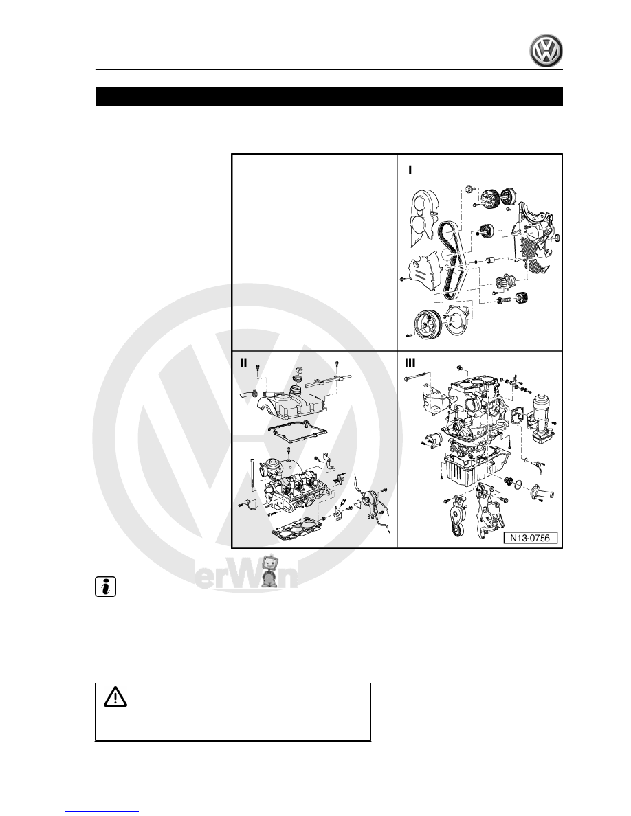
Engine - dismantle and assemble

Note

♦

Where large quantities of metal shavings and filings are de‐

tected in the engine oil during repair required as a result of

crankshaft and connecting rod bearing wear, the oil filter must

be replaced and the oil channels carefully cleaned.

♦

All bearing and running surfaces must be lubricated before

assembly.

WARNING

Always replace self-locking nuts and screws subject to angular

torque

Fox 2004 ➤

1. Engine - dismantle and assemble     

9


II 

⇒ page 11

III 

⇒ page 12

Part I

1 - Timing belt guard - upper

part
2 - Timing belt

❑ Mark rotation direction

before removal.

❑ Check wear.
❑ Do not bend.
❑ Remove, install, and ad‐

just 

⇒ page 41

 .

3 - 20 Nm +45°

❑ Replace after each

remova.l

4 - Timing belt tension pulley
5 - 100 Nm
6 - 25 Nm
7 - Camshaft gear
8 - Pulley

❑ Engine speed sensor.
❑ Immobilise with Coun‐

ter-hold tool -T10051- to

loosen or tighten.

❑ To remove, use Extrac‐

tor -T10052- .

❑ Remove and install

⇒ page 58

 .

9 - 10 Nm
10 - Mechanical distribution

rear cover
11 - Sealing ring

❑ Replace if damaged.

12 - Pulley
13 - Water pump

❑ Remove and install 

⇒ page 80

 .

14 - Crankshaft gear
15 - 120 Nm + 90°

❑ Replace after each removal..
❑ Immobilise with Lock -3415- to loosen or tighten.
❑ Do not apply additional oil or grease to the threads and recess/flanges.
❑ The angular torque can be performed in several stages.

Fox 2004 ➤

10


20 - 10 Nm + 90°

❑ Replace after each removal.

21 - Timing belt guard - centre part

Part II

1 - Cylinder head cover

❑ With oil filler nozzle.
❑ Replace oil filling nozzle

if cylinder head cover is

damaged.

❑ Before installation,

carefully clean the cylin‐

der head sealing sur‐

face with a clean cloth.

2 - To turbocharger
3 - 10 Nm

❑ First, hand tighten all

bolts.

❑ Then, tighten both top

and remaining bolts

from the inside out, di‐

agonally, to specified

tightening torque.

4 - Pressure regulating valve

❑ To crankcase vent.

5 - Cover

❑ Replace seal if dam‐

aged.

6 - Gasket

❑ Replace if damaged.

7 - Oil filling nozzle

❑ Replace.

8 - Engine and gearbox sup‐

port

❑ With fuel tube.

9 - Cylinder head cover gasket

❑ Replace if damaged.

10 - 20 Nm
11 - Lifting eye
12 - 10 Nm
13 - Central connector

❑ To injector

14 - From servo brake

Fox 2004 ➤

1. Engine - dismantle and assemble     

11


⇒ page 97

 .

❑ Check 

⇒ page 95

 .

16 - 25 Nm
17 - Supply hose

❑ From fuel filter 

⇒ Item 1 (page 87)

 .

❑ White or with white marking.
❑ Check that it is securely installed.
❑ Fasten with spring braces.

18 - Return hose

❑ To fuel filter 

⇒ Item 1 (page 87)

 .

❑ Blue or blue marked.
❑ Check that it is securely installed.
❑ Fasten with spring braces.

19 - Gasket

❑ Replace.

20 - Pin 10 Nm

❑ To engine cover.

21 - Engine and gearbox support
22 - Hexagonal nut
23 - Cylinder head gasket

❑ Replace.
❑ Observe identification 

⇒ page 35

 .

❑ When replacing, use completely new coolant.

24 - Hall Sensor -G40-

❑ To the camshaft position.
❑ Loosen to remove sealing ring from the mechanical distribution rear cover.

25 - Cylinder head securing bolt

❑ Replace.
❑ Follow the installation and removal sequence 

⇒ page 46

 .

❑ Insert washers into cylinder head before installing.

26 - Injectors

❑ Remove and install 

⇒ page 112

 .

Part III

WARNING

Always replace self-locking nuts and screws subject to angular

torque

Fox 2004 ➤

12


Content   ..  1  2  3  4  ..