Volkswagen Fox (2004 year). Manual - part 2
 

  Index      Volkswagen     Volkswagen Fox - service repair manual 2004 year


Search            copyright infringement  


Content   ..  1  2  3   ..


Volkswagen Fox (2004 year). Manual - part 2


pliers -VAS 5024A- .

– Remove/disconnect all the electric connections from the en‐

gine where necessary.

– Remove all the cooling, vacuum and intake system hoses from

the engine.

– Remove securing bolt of the cable support bracket and secure

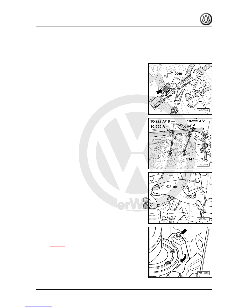
clutch release lever by inserting a Locking pin -T10060 A-

-arrow-.

– Remove securing bolts from the top of engine/gearbox.
– Remove cooling fluid container.
– Unbolt starter motor and move it back until the Support -3147-

can be inserted.

– Install the Support bracket -10-222A- and support engine and

gearbox as shown in diagram.

clamp and push exhaust pipe backwards 

⇒ page 118

 .

– Remove the protection plate behind the drive shaft flange.
Vehicles with air conditioning:
– For removal, refer to the additional information and instruc‐

tions 

⇒ page 8

 .

Fox 2004 ➤

1. Engine - remove and install    

5


the illustration -arrows-.

– Then, secure the Engine bracket -T10012- with nut -3- and

securing bolt from the compact bracket on the engine block.

Note

Place two A 10.5 X 21 X 2 Washers between engine bracket and

compact bracket so that the engine bracket lies flat on the com‐

pact bracket.

– Remove securing bolts from the bottom of engine/gearbox.
– Lift engine and gearbox lightly using the Gearbox or Engine +

gearbox combo jack -VAG 1383A-

– Remove the spindle of the Support bracket -10-222A- on the

engine side.

Note

Use Stepladder -VAS 5058- to remove the spindle.

– Separate engine from gearbox by carefully lowering it and us‐

ing the Gearbox or Engine + gearbox combo jack -VAG

1383A;- remove it from below.

Note

When lowering, handle the engine carefully to prevent damaging

the body.

1.2

Engine - fix on assembly stand

To perform the assembly work, the Engine and gearbox support

-VW 540- must be fastened on the assembly stand -VW 313- .

Fox 2004 ➤

6


Pulley side: 4th hole of the bar in position 1.
Engine flywheel side: 2nd hole of the bar in position 8.

WARNING

On hooks and pins, use safety locks -arrows-.

Note

♦

Positions numbered 1...4 on suspension bar face toward the

pulley.

♦

Drilled holes on supports are counted from the hook.

– Fasten the engine with the Support -VW 540- on the Stand -

VW 313- .

1.3

Notes regarding installation

Installation is carried out by reversing the removal sequence,

considering the following:
– Check clutch bearing for wear, replace if necessary.
– Apply a light coat of Lubricating grease -G 000 100 - on the

clutch bearing and on the primary shaft bearing guide sleeve.

– Check if guides for fastening engine and transmission are

placed on the engine block and, if necessary, install them.

– Align engine, moving it slightly so that the supports are seated

without stress.

Note

Assembly support tightening torques 

⇒ page 8

 .

bolt.

⇒ page 118

 .

– Install Poly-V belt 

⇒ page 14

 .

– Install air filter/turbocharger, intercooler/turbocharger and in‐

tercooler/intake flange hoses.

– Fill cooling system 

⇒ page 76

 .

⇒ page 115

 .

Fox 2004 ➤

1. Engine - remove and install    

7


Location


Tightening tor‐

que

Screws, nuts

M 6

10 Nm


M 8

20 Nm


M 10

45 Nm


M 12

60 Nm

Different tightening torques


Front exhaust and turbocharger pipe

25 Nm

1.5

Supports for the power drive group

Tightening torque

WARNING

Always replace self-locking nuts and screws subject to angular

torque

Power drive group suport, engine
1 -

1)

 = 30 Nm + 90°.

2 -

1)

 = 40 Nm + 90°.

3 - 45 Nm.

1)  Replace.

1.6

Additional removal information and in‐

structions for vehicles with air condition‐

ing

Note

♦

The air conditioning cooling gas circuit must be opened in or‐

der to remove the engine.

♦

To prevent damages to condenser and cooling gas hoses, do

not fold, twist or overstretch the hoses.

– Remove air conditioning compressor and anchor it to the body.

– Purge the cooling gas from air conditioning circuit and open

Note

The air conditioning compressor may remain fitted in its place.

Fox 2004 ➤

8


Content   ..  1  2  3   ..