Toyota RAV4 Hybrid (2021 year). Manual in english - part 6


  Index      Toyota     Toyota RAV4 Hybrid (2021 year). Manual in english


Search            copyright infringement  


Content      ..     4      5      6      7     ..


Toyota RAV4 Hybrid (2021 year). Manual in english - part 6


336

4-5. Using the driving support systems

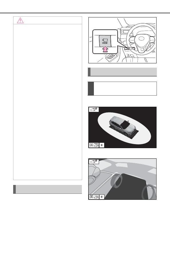
The camera switch is located as 
shown in the illustration.

Moving view

See-through view

NOTICE

People and other three-dimen-

sional obstacles may appear 

differently when displayed on 

the panoramic view monitor. 

(These differences include, 

among others, cases in which 

displayed objects appear to 

have fallen over, disappear near 

image processing areas, appear 

from image processing areas, 

or when the actual distance to 

an object differs from the dis-

played position.)

When the back door, which is 

equipped with the back camera, 

or front doors, which are 

equipped with door mirrors that 

have built-in side cameras, are 

open, images will not be dis-

played properly on the pan-

oramic view monitor.

The vehicle icon displayed in 

panoramic view/moving 

view/see-through view is a com-

puter generated image. Accord-

ingly, properties such as the 

color, shape and size will differ 

from the actual vehicle. For this 

reason, nearby three-dimen-

sional objects may appear to be 

touching the vehicle, and actual 

distances to three-dimensional 

objects may differ from those 

displayed.

Camera switch

Display

Checking around the vehi-
cle

-------------------------------------------------------------------------------------------------------------------------------------------------------------

337

4-5. Using the driving support systems

4

Driving

Wide front view & panoramic 
view

Rear view & panoramic view

Wide front view & side views

Side views

Rear view & side views

When you press the camera switch or shift the shift lever to the “R” 
position while the power switch is in ON, the panoramic view monitor 
operates.
The monitor displays various views of the position of the vehicle. 
(The following is an example)

Checking the front and 
around the vehicle

Checking the rear and 
around the vehicle

When folding the outside 
rear view mirrors

How to switch the display

-------------------------------------------------------------------------------------------------------------------------------------------------------------

338

4-5. Using the driving support systems

Audio screen, etc.

Moving view

See-through view

Audio screen, etc.

Wide front view & panoramic view

Side views

When the shift lever is in the “P” position

When the shift lever is in the “D” or “N” position

A

B

C

A

B

C

-------------------------------------------------------------------------------------------------------------------------------------------------------------

339

4-5. Using the driving support systems

4

Driving

Rear view & panoramic view

Wide rear view

Rear view

The moving view screen and the 
see-through view screen pro-
vide support when checking the 
areas of around the vehicle 
while parking. These screens 
display an image of the vicinity 
of the vehicle combined from the 
4 cameras. The screen will dis-
play a 360° view around the 
vehicle from either inside the 
vehicle or from a birds-eye view 
at an angle.
To display the moving view/see-
through view screen, press the 
camera switch when the shift 
lever is in the “P” position and 
the intuitive parking assist is 

enabled.

Moving view

Display mode switching but-
ton

Select to change the display mode 
between the moving view and the 
see-through view.

Rotation pause switch

Select to pause the rotation of the 

When the shift lever is in the “R” position

A

B

C

Checking around the 
vehicle

Screen display

A

B

-------------------------------------------------------------------------------------------------------------------------------------------------------------

340

4-5. Using the driving support systems

screen.

To resume rotation, select 

.

Body color setting switch

Select to display the body color set-
ting screen and change the color of 
the vehicle displayed on the pan-
oramic view monitor. (

P.353)

See-through view

Display mode switching but-

ton

Select to change the display mode 
between the moving view and the 
see-through view.

Rotation pause switch

Select to pause the rotation of the 
screen.

To resume rotation, select 

.

Body color setting switch

Select to display the body color set-
ting screen and change the color of 
the vehicle displayed on the pan-
oramic view monitor. (

P.353)

Pressing the camera switch again 

changes the screen back to the 

previously displayed screen, such 

as the audio screen.

The wide front view & panoramic view screen provides support when 
checking the areas in front of the vehicle and around the vehicle 
when taking-off at T-intersections or other intersections during poor 
visibility.
To display the screen, press the camera switch when the shift lever 
is in the “N” or “D” position with the vehicle moving approximately 7 
mph (12 km/h) or less.
This screen will be displayed if the intuitive parking assist detects an 
object in front of your vehicle (intuitive parking assist linked display).

C

A

B

C

Checking the front and around the vehicle

-------------------------------------------------------------------------------------------------------------------------------------------------------------

341

4-5. Using the driving support systems

4

Driving

Wide front view & panoramic view

Distance guide lines

Shows distance in front of the vehicle.
• Display points approximately 3 ft. (1 m) from the edge of the bumper.

Intuitive parking assist

When a sensor detects an obstacle, the direction of and the approximate 
distance to the obstacle are displayed and the buzzer sounds.

Estimated course lines

Shows an estimated course when the steering wheel is turned.
• This line will be displayed when the steering wheel is turned by 90° or 

more from the center (straight-line) position.

Guide line switching button

Select to change the guide line mode between the distance guide line 
mode and the estimated course line mode. (

P.342)

Automatic display button

Select to turn automatic display mode on/off. The indicator on the button 
illuminates during automatic display mode. (

P.342)

Parking Support Brake

*

When the system determines that the possibility of a frontal collision with a 
detected object is high, a warning message is displayed.

*

: If equipped

Pressing the camera switch changes the screen to the side views screen 

or previously displayed screen, such as the audio screen.

For details about the intuitive parking assist (

P.291) and Parking Sup-

port Brake

*

 function. (

P.298)

The display position of the intuitive parking assist and the position of 

obstacles displayed in the camera image do not match.

Screen display

A

B

C

D

E

F

-------------------------------------------------------------------------------------------------------------------------------------------------------------

342

4-5. Using the driving support systems

*

: If equipped

Each time the guide line switch-
ing button is selected, the mode 
will change as follows:

Distance guide line

Only the distance guide lines 
are displayed.

Estimated course line

Estimated course lines will be 
added to the distance guide 
lines.

In addition to screen switching 
by operating the camera switch, 
automatic display mode is avail-
able. In this mode, the screen is 
switched automatically in 
response to vehicle speed.
In automatic display mode, the 
monitor will automatically dis-
play images in the following situ-
ations:

When the shift lever is shifted 
to “N” or “D” position.

When vehicle speed is 
reduced to approximately 6 
mph (10 km/h) or less.

The side view screen displays images from the cameras installed on 

WARNING

When a sensor indicator on the intuitive parking assist display illumi-

nates in red or a buzzer sounds continuously, be sure to check the area 

around the vehicle immediately and do not proceed any further until 

safety has been ensured, otherwise an unexpected accident may occur.

As the intuitive parking assist display is displayed over the camera view, 

it may be difficult to see the intuitive parking assist display depending on 

the color and brightness of the surrounding area.

Switching the guide line 
mode

Automatic display mode

Checking the sides of the vehicle

-------------------------------------------------------------------------------------------------------------------------------------------------------------

343

4-5. Using the driving support systems

4

Driving

each outside rear view mirror. This screen is designed to support the 
driver in safe driving in situations such as when driving on a narrow 
road, by allowing them to check the areas around the sides of the 
vehicle.
To display the screen, press the camera switch when the shift lever 
is in the “D”, or “N” position with the vehicle moving approximately 7 
mph (12 km/h) or less.

Side view

Distance guide lines

Show distance in front of the vehicle.
• Display points approximately 3 ft. (1 m) from the edge of the bumper.

Vehicle width guide lines

Shows guide lines of the vehicle’s width including the outside rear view mir-
rors.

Front tire guide lines

Shows guide lines of where the front tire touches the ground.

Automatic display button

Select to turn automatic display mode on/off. The indicator on the button 
illuminates during automatic display mode. (

P.344)

Intuitive parking assist

When a sensor detects an obstacle, the direction of and the approximate 
distance to the obstacle are displayed and the buzzer sounds.

Pressing the camera switch changes the screen to the wide front view & 

panoramic view screen or previously displayed screen, such as the audio 

screen.

For details about the intuitive parking assist. (

P.291)

Screen display

A

B

C

D

E

-------------------------------------------------------------------------------------------------------------------------------------------------------------

344

4-5. Using the driving support systems

The side views can be displayed even when the outside rear view mirrors 

are retracted.

In addition to screen switching 
by operating the camera switch, 
automatic display mode is avail-
able. In this mode, the screen is 
switched automatically in 
response to vehicle speed.
In automatic display mode, the 
monitor will automatically dis-
play images in the following situ-
ations:

When the shift lever is shifted 
to “N” or “D” position.

When vehicle speed is 
reduced to approximately 6 
mph (12 km/h) or less.

Side View

Check the positions and dis-
tance between the vehicle 
width guide line and a target 
object such as the obstacle or 
curb of the road.

WARNING

When a sensor indicator on the intuitive parking assist display illumi-

nates in red or a buzzer sounds continuously, be sure to check the area 

around the vehicle immediately and do not proceed any further until 

safety has been ensured, otherwise an unexpected accident may occur.

As the intuitive parking assist display is displayed over the camera view, 

it may be difficult to see the intuitive parking assist display depending on 

the color and brightness of the surrounding area.

Automatic display mode

Using the vehicle width 
guide line

-------------------------------------------------------------------------------------------------------------------------------------------------------------

345

4-5. Using the driving support systems

4

Driving

Pull over to the curb as shown 
in the illustration above, tak-
ing care not to let the vehicle 
width guide line overlap the 

target object.

Ensure that the vehicle width 
guide line is parallel to the tar-
get object.

The rear view & panoramic view screen, the wide rear view screen 
and the rear view screen provide support when checking the areas 
of behind the vehicle and around the vehicle while backing up, for 
example while parking.
The screens will be displayed when the shift lever is in the “R” posi-
tion.

Each time the display mode switching button is selected, the mode 
will change as follows:

Checking the rear and around the vehicle

Screen display

-------------------------------------------------------------------------------------------------------------------------------------------------------------

346

4-5. Using the driving support systems

Rear view & panoramic view

Intuitive parking assist

When a sensor detects an obstacle, the direction of and the approximate 
distance to the obstacle are displayed and the buzzer sounds.

Rear Cross Traffic Alert

When a sensor detects an obstacle, the direction of obstacle is displayed 
and the buzzer sounds.

Guide line switching button

Select to switch the guide line mode. (

P.348)

Display mode switching button

Each time the display mode switching button is selected, the mode will 
change between the rear view & panoramic view mode, the wide rear view 
mode and rear view mode.

Parking Support Brake

*

When the system determines that the possibility of a collision with a 
detected object is high, a warning message is displayed.

*

: If equipped

Wide rear view

Intuitive parking assist

When a sensor detects an obstacle, the direction of and the approximate 

A

B

C

D

E

A

-------------------------------------------------------------------------------------------------------------------------------------------------------------

347

4-5. Using the driving support systems

4

Driving

distance to the obstacle are displayed and the buzzer sounds.

Rear Cross Traffic Alert

When a sensor detects an obstacle, the direction of obstacle is displayed 
and the buzzer sounds.

Guide line switching button

Select to switch the guide line mode. (

P.348)

Display mode switching button

Each time the display mode switching button is selected, the mode will 
change between the rear view & panoramic view mode, the wide rear view 
mode and rear view mode.

Parking Support Brake

*

When the system determines that the possibility of a collision with a 
detected object is high, a warning message is displayed.

*

: If equipped

Rear view

Intuitive parking assist

When a sensor detects an obstacle, the direction of and the approximate 
distance to the obstacle are displayed and the buzzer sounds.

Rear Cross Traffic Alert

When a sensor detects an obstacle, the direction of obstacle is displayed 
and the buzzer sounds.

Guide line switching button

Select to switch the guide line mode. (

P.348)

Display mode switching button

Each time the display mode switching button is selected, the mode will 
change between the rear view & panoramic view mode, the wide rear view 
mode and rear view mode.

Parking Support Brake

*

B

C

D

E

A

B

C

D

E

-------------------------------------------------------------------------------------------------------------------------------------------------------------

348

4-5. Using the driving support systems

When the system determines that the possibility of a collision with a 
detected object is high, a warning message is displayed.

*

: If equipped

The monitor is canceled when the shift lever is shifted into any position 

other than the “R” position.

For details about the intuitive parking assist (

P.291), Rear Cross Traffic 

Alert function (

P.288) and Parking Support Brake

*

 function. (

P.298)

The display position of the intuitive parking assist and the position of 

obstacles displayed in the camera image do not match.

*

: If equipped

Each time the guide line switching button is selected, the mode will 
change as follows:

Estimated course line

Estimated course lines are displayed which move in accordance with 
the operation of the steering wheel.

Distance guide lines

Shows distance in front of the vehicle.
• Display points approximately 3 ft. (1 m) from the edge of the bumper.

WARNING

When a sensor indicator on the intuitive parking assist display illumi-

nates in red or a buzzer sounds continuously, be sure to check the area 

around the vehicle immediately and do not proceed any further until 

safety has been ensured, otherwise an unexpected accident may occur.

As the intuitive parking assist display and Rear Cross Traffic Alert dis-

play are displayed over the camera view, it may be difficult to see the 

intuitive parking assist display and Rear Cross Traffic Alert display 

depending on the color and brightness of the surrounding area.

Guide lines displayed on the screen

A

-------------------------------------------------------------------------------------------------------------------------------------------------------------

349

4-5. Using the driving support systems

4

Driving

Estimated course lines

Shows an estimated course when the steering wheel is turned.

Distance guide lines

Shows the distance behind the vehicle when the steering wheel is turned.
• The guide lines move in conjunction with the estimated course lines.
• The guide lines display points approximately 1.5 ft. (0.5 m) (red) and 

approximately 3 ft. (1 m) (yellow) from the center of the edge of the 
bumper.

Distance guide line

Shows the distance behind the vehicle.
• Displays a point approximately 1.5 ft. (0.5 m) (blue) from the edge of the 

bumper.

Vehicle width guide lines

Displays a guide path when the vehicle is being backed straight up.

Vehicle center guide line

Indicates the estimated vehicle center on the ground.

Parking assist guide line

The steering wheel return points (parking assist guide lines) are dis-
played.
This mode is recommended for those who are comfortable with park-
ing the vehicle without the aid of the estimated course lines.

Distance guide lines

Shows distance in front of the vehicle.
• Display points approximately 3 ft. (1 m) from the edge of the bumper.

Distance guide line

Shows the distance behind the vehicle.
• Displays a point approximately 1.5 ft. (0.5 m) (red) from the edge of the 

bumper.

B

C

D

E

F

A

B

-------------------------------------------------------------------------------------------------------------------------------------------------------------

350

4-5. Using the driving support systems

Vehicle center guide line

Indicates the estimated vehicle center on the ground.

Vehicle width guide lines

Displays a guide path when the vehicle is being backed straight up.

Parking assist guide lines

Shows the path of the smallest turn possible behind the vehicle.

Distance guide line

Only distance guide line is displayed.
This mode is recommended for those who are comfortable with park-
ing the vehicle without the aid of the guide lines.

Distance guide lines

Shows distance in front of the vehicle.
• Display points approximately 3 ft. (1 m) from the edge of the bumper.

Distance guide line

Shows the distance behind the vehicle.
• Displays a point approximately 1.5 ft. (0.5 m) (red) from the edge of the 

bumper.

The display position of the intuitive parking assist and the position of 

obstacles displayed in the camera image do not match.

WARNING

Depending on the circumstances of the vehicle (number of passengers, 

amount of luggage, etc.), the position of the guide lines displayed on the 

screen may change. Be sure to check visually around the vehicle before 

proceeding.

If the steering wheel is straight and the vehicle width guide lines and the 

estimated course lines are not in alignment, have the vehicle inspected 

by your Toyota dealer.

C

D

E

A

B

-------------------------------------------------------------------------------------------------------------------------------------------------------------

351

4-5. Using the driving support systems

4

Driving

When parking in a space which 
is in the reverse direction to the 
space described in the proce-
dure below, the steering direc-
tions will be reversed.

1

Shift the shift lever to the “R” 
position.

2

Turn the steering wheel so 
that the estimated course 
lines are within the parking 
space, and back up slowly.

Parking space

Estimated course lines

3

When the rear position of the 
vehicle has entered the park-
ing space, turn the steering 
wheel so that the vehicle 
width guide lines are within 
the left and right dividing 
lines of the parking space.

Vehicle width guide line

4

Once the vehicle width guide 
lines and the parking space 
lines are parallel, straighten 
the steering wheel and back 
up slowly until the vehicle 
has completely entered the 
parking space.

WARNING

Do not use the system if the display is incorrect due to an uneven (hilly) 

road or a non-straight (curvy) road.

Parking

Using the estimated course 
line

A

B

A

-------------------------------------------------------------------------------------------------------------------------------------------------------------

352

4-5. Using the driving support systems

5

Stop the vehicle in an appro-
priate place, and finish park-
ing.

When parking in a space which 
is in the reverse direction to the 
space described in the proce-
dure below, the steering direc-
tions will be reversed.

1

Shift the shift lever to the “R” 
position.

2

Back up until the parking 
assist guide line meets the 
edge of the dividing line of 
the parking space.

Parking assist guide line

Parking space dividing line

3

Turn the steering wheel all 
the way to the left, and back 
up slowly.

4

Once the vehicle is parallel 
with the parking space, 
straighten the steering wheel 
and back up slowly until the 
vehicle has completely 
entered the parking space.

5

Stop the vehicle in an appro-
priate place, and finish park-
ing.

Even when outside rear view 
mirrors are stored, the monitor 
can display various images of 
the vicinity of the vehicle and 
assist the operation in the con-
firming safe conditions in a nar-
row places, parking, etc.

Wide front view & side views

Using parking assist guide 
line

A

B

When folding the outside 
rear view mirrors

Screen display

-------------------------------------------------------------------------------------------------------------------------------------------------------------

353

4-5. Using the driving support systems

4

Driving

Rear view & side views

Intuitive parking assist

When a sensor detects an obsta-
cle, the direction of and the approx-
imate distance to the obstacle are 
displayed and the buzzer sounds.

For details about the front view 

and the rear view: 

P.340, 345

If displayed objects are too 
small to see clearly when the 
panoramic view is displayed, the 
area around any of the 4 cor-
ners of the vehicle can be mag-
nified.

1

Turn the intuitive parking 
assist on.

2

Select the area on the pan-
oramic view display you wish 
to magnify.

Touching one of the 4 areas 
within the dotted lines will 
magnify that area. (Dotted 
lines are not displayed on the 
actual display.)

To return to the normal view, 
touch the panoramic view dis-
play again.

The magnifying function is 

enabled when all of the following 

conditions are met:

• The wide front view & panoramic 

view or the rear view & panoramic 

view is displayed.

• The vehicle speed is below 

approximately 7 mph (12 km/h).

• The intuitive parking assist is 

available.

In the following situations, the 

magnified display will be can-

celed automatically:

• The vehicle speed is approxi-

mately 7 mph (12 km/h) or higher.

• The intuitive parking assist is 

unavailable.

When the display is magnified, the 

guide lines will not be displayed.

The color of the vehicle dis-

WARNING

When a sensor indicator on the 

intuitive parking assist display 

illuminates in red or a buzzer 

sounds continuously, be sure to 

check the area around the vehi-

cle immediately and do not pro-

ceed any further until safety has 

been ensured, otherwise an 

unexpected accident may 

occur.

Magnifying function

Magnifying the display

A

Customizing the pan-
oramic view monitor

-------------------------------------------------------------------------------------------------------------------------------------------------------------

354

4-5. Using the driving support systems

played on the panoramic view 
monitor can be changed.

1

Display the moving view/see-
through view screen. 
(

P.339)

2

Select 

.

3

Select the desired color.

Displays the next page

The panoramic view monitor displays an image of the surrounding 
view of the vehicle.
Since the panoramic view processes and displays images based on 
flat road surfaces, it cannot depict the position of three-dimension 
objects (such as vehicle bumpers, etc.) that are in positions higher 
than the surface of the road. Even if there is room between the bum-
pers of the vehicles and it seems not likely to collide in the image, in 
reality, the both vehicles are on a collision course.
Check the safety of the surroundings directly.

Objects located in the shaded areas will not be displayed on the 
screen.

Changing the body color 
displayed in the pan-
oramic view monitor

A

Panoramic view monitor precautions

Area displayed on screen

Area of image of panoramic view

A

-------------------------------------------------------------------------------------------------------------------------------------------------------------

355

4-5. Using the driving support systems

4

Driving

Parts of objects which extend above a certain height cannot be 
displayed on the screen.

As the images obtained from four cameras are processed and displayed 

on the standard of a flat road surface; the panoramic view/moving 

view/see through view may be displayed as follows.

• Objects may look collapsed; thinner or bigger than usual.

• An object with a higher position than the road surface may look farther 

away than it actually is or may not appear at all.

• Tall objects may appear protruding from the non-displayed areas of the 

image.

Variations in the brightness of the image may appear for every camera.

The displayed image may be shifted by inclination of the vehicle body, 

change in vehicle height, etc., depending on the number of passengers, 

amount of luggage, fuel quantity, etc.

If the front doors or back door are not completely closed; neither the 

image nor the guide lines are displayed.

The position relations of the vehicle icon and the road surface or obstacle 

may differ from the actual positions.

The black areas of the vicinity of the vehicle icon are areas that are not 

captured by the camera.

Images like the following are combined, thus some areas may be difficult 

to view.

A

-------------------------------------------------------------------------------------------------------------------------------------------------------------

356

4-5. Using the driving support systems

Wide front view

Side view

WARNING

When a sensor indicator on the intuitive parking assist display illumi-

nates in red or a buzzer sounds continuously, be sure to check the area 

around the vehicle immediately and do not proceed any further until 

safety has been ensured, otherwise an unexpected accident may occur.

Area of the image captured 
by the camera

-------------------------------------------------------------------------------------------------------------------------------------------------------------

357

4-5. Using the driving support systems

4

Driving

Rear view

The area around both cor-
ners of the bumper will not be 
displayed.

Wide rear view

The area around both cor-

ners of the bumper will not be 
displayed.

Black masking is done for dis-

tance detection differences to the 

front of the vehicle.

The area covered by the camera 

is limited. Objects which are close 

to either corner of the bumper or 

under the bumper cannot be seen 

on the screen.

The area displayed on the screen 

may vary depending on vehicle 

orientation or road conditions.

The camera uses a special lens. 

The distance in the image dis-

played on the screen will differ 

from the actual distance.

The cameras for the panoramic 
view monitor are located as 
shown in the illustrations.

Front camera

Side cameras

A

A

The camera

-------------------------------------------------------------------------------------------------------------------------------------------------------------

358

4-5. Using the driving support systems

Rear camera

If dirt or foreign matter (such as 
water droplets, snow, mud, etc.) 
is adhering to the camera, it 
cannot transmit a clear image. 
In this case, flush it with a large 
quantity of water and wipe the 
camera lens clean with a soft 
and wet cloth.

The distance guide lines and 
the vehicle width guide lines 

Using the camera

NOTICE

The panoramic view monitor 

may not operate properly in the 

following cases.

• If the camera is hit, the position 

and mounting angle of the cam-

era may change.

• As the camera has a water 

proof construction, do not 

detach, disassemble or modify 

it. This may cause incorrect 

operation.

• When cleaning the camera lens, 

flush the camera with a large 

quantity of water and wipe it 

with a soft and wet cloth. 

Strongly rubbing the camera 

lens may cause the camera lens 

to be scratched and unable to 

transmit a clear image.

• Do not allow an organic solvent, 

car wax, window cleaner or a 

glass coating to adhere to the 

camera. If this happens, wipe it 

off as soon as possible.

• If the temperature changes rap-

idly, such as when hot water is 

poured on the vehicle in cold 

weather, the system may not 

operate normally.

• When washing the vehicle, do 

not apply intensive bursts of 

water to the camera or camera 

area. Doing so may result in the 

camera malfunctioning.

Do not expose the camera to 

strong impacts as this could 

cause a malfunction. If this hap-

pens, have the vehicle 

inspected by your Toyota dealer 

as soon as possible.

Difference between the 
screen and the actual road

-------------------------------------------------------------------------------------------------------------------------------------------------------------

359

4-5. Using the driving support systems

4

Driving

may not actually be parallel 
with the dividing lines of the 
parking space, even when 
they appear to be so. Be sure 
to check visually.

The distances between the 
vehicle width guide lines and 
the left and right dividing lines 
of the parking space may not 
be equal, even when they 
appear to be so. Be sure to 
check visually.

The distance guide lines give 
a distance guide for flat road 
surfaces. In any of the follow-
ing situations, there is a mar-
gin of error between the guide 
lines on the screen and the 
actual distance/course on the 
road.

The distance guide lines will 
appear to be closer to the vehi-
cle than the actual distance. 
Because of this, objects will 
appear to be farther away than 
they actually are. In the same 
way, there will be a margin of 
error between the guidelines 
and the actual distance/course 
on the road.

The distance guide lines will 
appear to be farther from the 
vehicle than the actual distance. 
Because of this, objects will 
appear to be closer than they 
actually are. In the same way, 
there will be a margin of error 
between the guidelines and the 
actual distance/course on the 
road.

When the ground behind the 
vehicle slopes up sharply

When the ground behind the 
vehicle slopes down sharply

-------------------------------------------------------------------------------------------------------------------------------------------------------------

360

4-5. Using the driving support systems

When any part of the vehicle 
sags due to the number of pas-
sengers or the distribution of the 
load, there is a margin of error 
between the guide lines on the 
screen and the actual dis-
tance/course on the road.

A margin of error

When there are three-dimensional objects (such as vehicle bum-
pers, etc.) nearby in positions higher than the surface of the road, 
take extra care when using the following.

Since the panoramic view processes and displays images based on 
flat road surfaces, it cannot depict the position of three-dimension 
objects (such as vehicle bumpers, etc.) that are in positions higher 
than the surface of the road. For example, even though it appears 
that there is space between the bumpers of the two vehicles in the 
illustration below and they are not likely to collide, in reality, a colli-
sion is about to occur.

When any part of the vehicle 
sags

A

Distortion of three-dimensional objects on the screen

Panoramic view display (including magnified display)

-------------------------------------------------------------------------------------------------------------------------------------------------------------

361

4-5. Using the driving support systems

4

Driving

The estimated course lines target flat surfaced objects (such as the 
road). It is not possible to determine the position of three-dimen-
sional objects (such as vehicles) using the estimated course lines 
and distance guide lines. When approaching a three-dimensional 
object that extends outward (such as the flatbed of a truck), be care-
ful of the following.

Since the estimated course line 
is displayed for a flat road sur-
face, it cannot depict the posi-
tion of three-dimensional objects 
(such as vehicle bumpers, etc.) 
that are in positions higher than 

the surface of the road. Even if 
the bumpers of the vehicle is on 
the outside of the estimated 
course line in the image, in real-
ity, the vehicles are on a colli-
sion course.

WARNING

When a sensor indicator on the intuitive parking assist display illumi-

nates in red or a buzzer sounds continuously, be sure to check the area 

around the vehicle immediately and do not proceed any further until 

safety has been ensured, otherwise an unexpected accident may occur.

When approaching three-dimensional objects

WARNING

When a sensor indicator on the intuitive parking assist display illumi-

nates in red or a buzzer sounds continuously, be sure to check the area 

around the vehicle immediately and do not proceed any further until 

safety has been ensured, otherwise an unexpected accident may occur.

Estimated course lines

-------------------------------------------------------------------------------------------------------------------------------------------------------------

362

4-5. Using the driving support systems

Estimated course line

Three-dimensional objects 
(such as the overhang of a wall 
or loading platform of a truck) in 
high positions may not be pro-
jected on the screen. Check the 
safety of the surroundings 
directly.

Visually check the surroundings 
and the area behind the vehicle. 
In the case shown below, the 
truck appears to be outside of 
the estimated course lines and 
the vehicle does not look as if it 
hits the truck. However, the rear 
body of the truck may actually 
cross over the estimated course 
lines. In reality if you back up as 
guided by the estimated course 
lines, the vehicle may hit the 
truck.

A

-------------------------------------------------------------------------------------------------------------------------------------------------------------

363

4-5. Using the driving support systems

4

Driving

Estimated course lines

Visually check the surroundings 
and the area behind the vehicle. 
On the screen, it appears that a 
truck is parking at point 

However, in reality if you back 

up to point 

, you will hit the 

truck. On the screen, it appears 
that 

 is closest and 

 is far-

thest away. However, in reality, 
the distance to 

 and 

 is the 

same, and 

 is farther than 


and 

.

If you notice any of the following symptoms, refer to the likely cause 
and the solution, and re-check.
If the symptom is not resolved by the solution, have the vehicle 
inspected by your Toyota dealer.

Distance guide lines

A

B

A

A

C

A

C

B

A

C

Things you should know

If you notice any symptoms

-------------------------------------------------------------------------------------------------------------------------------------------------------------

364

4-5. Using the driving support systems

Symptom

Likely cause

Solution

The image is difficult to 
see

The vehicle is in a 
dark area

The temperature 
around the lens is 
either high or low

The outside tempera-
ture is low

There are water drop-
lets on the camera

It is raining or humid

Foreign matter (mud, 
etc.) is adhering to the 
camera

Sunlight or headlights 
are shining directly 
into the camera

The vehicle is under 
fluorescent lights, 
sodium lights, mer-
cury lights, etc.

Back up while visually 
checking the vehicle’s 
surroundings. (Use the 
monitor again once con-
ditions have been 
improved.)
The procedure for 
adjusting the picture 
quality of the pan-
oramic view monitor 
system is the same as 
the procedure for 
adjusting the screen dis-
play. (

P.400)

The image is blurry

Dirt or foreign matter 
(such as water drop-
lets, snow, mud, etc.) is 
adhering to the camera.

Flush the camera with a 
large quantity of water 
and wipe the camera 
lens clean with a soft 
and wet cloth.

The image is out of 
alignment

The camera or sur-
rounding area has 
received a strong 
impact.

Have the vehicle 
inspected by your 
Toyota dealer.

The guide lines are very 
far out of alignment

The camera position is 
out of alignment.

Have the vehicle 
inspected by your 
Toyota dealer.

The vehicle is tilted. 
(There is a heavy load 
on the vehicle, tire 
pressure is low due to 
a tire puncture, etc.)

The vehicle is used on 
an incline.

If this happens due to 
these causes, it does 
not indicate a malfunc-
tion.
Back up while visually 
checking the vehicle’s 
surroundings.

-------------------------------------------------------------------------------------------------------------------------------------------------------------

365

4-5. Using the driving support systems

4

Driving

The estimated course 
lines move even though 
the steering wheel is 
straight

There is a malfunction 
in the signals being out-
put by the steering sen-
sor.

Have the vehicle 
inspected by your 
Toyota dealer.

Guide lines are not dis-
played

The back door is open.

Close the back door.
If this does not resolve 
the symptom, have the 
vehicle inspected by 
your Toyota dealer.

The estimated course 
lines are not displayed

12-volt battery has 
been reinstalled.

The steering wheel 
has been moved while 
the 12-volt battery 
was being reinstalled.

12-volt battery power 
is low.

The steering sensor 
has been reinstalled.

There is a malfunction 
in the signals being 
output by the steering 
sensor.

Have the vehicle 
inspected by your 
Toyota dealer.

The panoramic view dis-
play cannot be magni-
fied

The intuitive parking 
assist may be malfunc-
tioning or dirty.

Follow the correction 
procedures for malfunc-
tions of the intuitive 
parking assist. 
(

P.291)

The see-through 
view/moving view can-
not be displayed

Product license

Symptom

Likely cause

Solution

-------------------------------------------------------------------------------------------------------------------------------------------------------------

366

4-5. Using the driving support systems

1

Eco drive mode

Suitable for driving to improve fuel 
economy by more smoothly gener-
ating torque in response to acceler-
ator pedal operations compared to 
normal mode and restraining air 
conditioning system operations 
(heating/cooling).
When the switch is turned to the left 
while not in Eco drive mode, the 
system switches to Eco drive mode 
and the Eco drive mode indicator 
illuminates on the multi-information 
display.

2

Normal mode

Suitable for normal driving.
The driving mode returns to normal 
mode if the switch is pressed while 
in Eco drive mode or sport mode.

3

Sport mode

Controls the steering feeling and 
hybrid system to create an acceler-
ation response that is suitable for 
sporty driving. Suitable for when 
crisp handling is desired, such as 
when driving on mountainous 
roads.
When the switch is turned to the 
right while not in sport mode, the 
system switches to sport mode and 
the sport mode indicator illuminates 
on the multi-information display.

When changing to a driving 

mode other than normal mode

The background color of the multi-

information display changes 

according to the selected driving 

mode.

When the speedometer is set to 

analog display, the speedometer 

display color also changes. (For 

vehicles with the 7-inch multi-

information display only)

The color of the switch changes 

according to the selected driving 

mode. (For vehicles with the 7-

inch multi-information display 

only)

Air conditioning system opera-

tion in Eco drive mode

In Eco drive mode, heating/cooling 

operations and the fan speed is con-

trolled to improve fuel efficiency. 

Perform the following procedures to 

increase the air conditioning perfor-

mance.

Turn eco air conditioning mode off 

(

P.525)

Adjust the fan speed (

P.525)

Cancel Eco drive mode

Driving mode select 

switch

The driving modes can be 
selected to suit the driving 
and usage conditions.

Selecting a driving mode

-------------------------------------------------------------------------------------------------------------------------------------------------------------

367

4-5. Using the driving support systems

4

Driving

Canceling a driving mode

Sport mode is automatically can-

celed and the driving mode 

returns to normal mode when the 

power switch is turned off.

Normal mode and Eco drive mode 

are not canceled until another 

driving mode is selected. (Even if 

the power switch is turned off, nor-

mal mode and Eco drive mode will 

not be automatically canceled).

Press the Trail Mode switch

When the switch is pressed, Trail 
Mode turns on and the Trail Mode 
indicator illuminates on the multi-
information display.
When the switch is pressed again, 
the Trail Mode indicator turns off.

Trail Mode

Trail Mode is a system that 
performs integrated control 
for the AWD, brake and 
drive force control systems 
to assist the drive power on 
bumpy roads, etc.

WARNING

Before using Trail Mode

Make sure to observe the follow-

ing precautions. Failure to 

observe these precautions may 

result in an unexpected accident.

Check that the Trail Mode indi-

cator is illuminated before driv-

ing. Trail Mode will not operate 

when the indicator is off.

Trail Mode is not intended to 

expand the limits of the vehicle. 

Thoroughly check the road con-

ditions and drive with caution.

Thoroughly check the road con-

ditions before driving. As Trail 

Mode is suitable for driving on 

bumpy roads, such as those 

where the tire on one side 

spins, there is a chance that 

Trail Mode may not be the most 

appropriate for other road con-

ditions.

Turning Trail Mode on

-------------------------------------------------------------------------------------------------------------------------------------------------------------

368

4-5. Using the driving support systems

Trail Mode

Trail Mode is intended for use 

when driving on bumpy rough 

roads. Do not turn the switch on in 

other situations.

Trail Mode controls the vehicle so 

that it can use the maximum 

amount of drive force when driving 

on bumpy roads.

If Trail Mode is continuously used 

for a long period of time, the load 

on related parts increases and the 

system may be unable to operate 

effectively.

When Trail Mode is canceled

In the following situations, Trail 

Mode is automatically canceled 

even if it is turned on.

When the driving mode is 

changed (

P.366)

When the power switch is turned 

off

During Trail Mode operation

The following types of situations 

may occur, but they are not mal-

functions.

Vibrations may be felt throughout 

the vehicle or steering wheel

Operating noise may be heard 

from the engine compartment

When an inspection at your 

Toyota dealer is necessary

In the following situations, the sys-

tem may be malfunctioning. Have 

the vehicle inspected by your 

Toyota dealer immediately.

When the slip indicator light illumi-

nates while Trail Mode is on

When the Trail Mode indicator 

does not illuminate even though 

the Trail Mode switch is pressed

-------------------------------------------------------------------------------------------------------------------------------------------------------------

369

4-5. Using the driving support systems

4

Driving

ECB (Electronically Con-
trolled Brake System)

The electronically controlled 
system generates braking force 
corresponding to the brake 
operation

ABS (Anti-lock Brake Sys-
tem)

Helps to prevent wheel lock 
when the brakes are applied 
suddenly, or if the brakes are 
applied while driving on a slip-
pery road surface

Brake assist

Generates an increased level of 
braking force after the brake 
pedal is depressed when the 
system detects a panic stop sit-
uation

VSC (Vehicle Stability Con-
trol)

Helps the driver to control skid-
ding when swerving suddenly or 
turning on slippery road sur-
faces.

Enhanced VSC (Enhanced 
Vehicle Stability Control)

Provides cooperative control of 
the ABS, TRAC, VSC and EPS.
Helps to maintain directional 
stability when swerving on slip-
pery road surfaces by con-
trolling steering performance.

Trailer Sway Control

Helps the driver to control trailer 
sway by selectively applying 
brake pressure for individual 
wheels and reducing driving 
torque when trailer sway is 
detected.

TRAC (Traction Control)

Helps to maintain drive power 
and prevent the drive wheels 
from spinning when starting the 
vehicle or accelerating on slip-
pery roads

Active Cornering Assist 
(ACA)

Helps to prevent the vehicle 
from drifting to the outer side by 
performing inner wheel brake 
control when attempting to 
accelerate while turning

Hill-start assist control

Helps to reduce the backward 

Driving assist systems

To keep driving safety and 
performance, the following 
systems operate automati-
cally in response to various 
driving situations. Be 
aware, however, that these 
systems are supplementary 
and should not be relied 
upon too heavily when oper-
ating the vehicle.

Summary of the driving 
assist systems

-------------------------------------------------------------------------------------------------------------------------------------------------------------

370

4-5. Using the driving support systems

movement of the vehicle when 
starting on an uphill

EPS (Electric Power Steer-
ing)

Employs an electric motor to 
reduce the amount of effort 
needed to turn the steering 
wheel

E-Four (Electronic On-
Demand AWD system)

Automatically switches from 
front wheel drive to all-wheel 
drive (AWD) according to the 
driving conditions, helping to 
ensure reliable handling and 
stability. Examples of condi-
tions where the system will 
switch to AWD are when corner-
ing, going uphill, starting off or 
accelerating, and when the road 
surface is slippery due to snow, 
rain, etc.

The Secondary Collision 
Brake

When the SRS airbag sensor 
detects a collision and the sys-
tem operates, the brakes and 
brake lights are automatically 
controlled to reduce the vehicle 
speed and help reduce the pos-
sibility of further damage due to 
a secondary collision.

When the 

TRAC/VSC/ABS/Trailer Sway 

Control systems are operating

The slip indicator light will flash 

while the TRAC/VSC/ABS/Trailer 

Sway Control systems are operat-

ing.

Disabling the TRAC system

If the vehicle gets stuck in mud, dirt 

or snow, the TRAC system may 

reduce power from the hybrid sys-

tem to the wheels.

Pressing 

 to turn the system off 

may make it easier for you to rock 

the vehicle in order to free it.
To turn the TRAC system off, 
quickly press and release 

.

“Traction Control Turned OFF” will 

be shown on the multi-information 

display.

Press 

 again to turn the system 

back on.

Turning off the 

TRAC/VSC/Trailer Sway Con-

trol systems

To turn the TRAC/VSC/Trailer Sway 

Control systems off, press and hold 

 for more than 3 seconds while 

the vehicle is stopped.
The VSC OFF indicator light will 

come on and the “Traction Control 

Turned OFF” will be shown on the 
multi-information display.

*

Press 

 again to turn the systems 

back on.

-------------------------------------------------------------------------------------------------------------------------------------------------------------

371

4-5. Using the driving support systems

4

Driving

*

: PCS will also be disabled (only 

Pre-Collision warning is avail-
able). The PCS warning light will 
come on and a message will be 
displayed on the multi-information 
display. (

P.257)

When the message is dis-

played on the multi-information 

display showing that TRAC has 
been disabled even if 

 has 

not been pressed

TRAC is temporary deactivated. If 

the information continues to show, 

contact your Toyota dealer.

Operating conditions of hill-

start assist control

When the following four conditions 

are met, the hill-start assist control 

will operate:

The shift lever is in a position 

other than P or N (when starting 

off forward/backward on an 

upward incline).

The vehicle is stopped.

The accelerator pedal is not 

depressed.

The parking brake is not engaged.

Automatic system cancelation 

of hill-start assist control

The hill-start assist control will turn 

off in any of the following situations:

The shift lever is shifted to P or N.

The accelerator pedal is 

depressed.

The parking brake is engaged.

No more than 2 seconds have 

elapsed after the brake pedal is 

released.

Sounds and vibrations caused 

by the ABS, brake assist, VSC, 

Trailer Sway Control, TRAC and 

hill-start assist control systems

A sound may be heard from the 

engine compartment when the 

brake pedal is depressed repeat-

edly, when the hybrid system is 

started or just after the vehicle 

begins to move. This sound does 

not indicate that a malfunction has 

occurred in any of these systems.

Any of the following conditions 

may occur when the above sys-

tems are operating. None of these 

indicates that a malfunction has 

occurred.

• Vibrations may be felt through the 

vehicle body and steering.

• A motor sound may be heard also 

after the vehicle comes to a stop.

ECB operating sound

ECB operating sound may be heard 

in the following cases, but it does 

not indicate that a malfunction has 

occurred.

Operating sound heard from the 

engine compartment when the 

brake pedal is operated.

Motor sound of the brake system 

heard from the front part of the 

vehicle when the driver’ door is 

opened.

Operating sound heard from the 

engine compartment when one or 

two minutes passed after the stop 

of the hybrid system.

Active Cornering Assist opera-

tion sounds and vibrations

When the Active Cornering Assist is 

operated, operation sounds and 

vibrations may be generated from 

the brake system, but this is not a 

malfunction.

EPS operation sound

When the steering wheel is oper-

ated, a motor sound (whirring 

sound) may be heard. This does not 

indicate a malfunction.

Automatic reactivation of 

TRAC, Trailer Sway Control and 

VSC systems

After turning the TRAC, Trailer 

Sway Control and VSC systems off, 

the systems will be automatically re-

enabled in the following situations:

-------------------------------------------------------------------------------------------------------------------------------------------------------------

372

4-5. Using the driving support systems

When the power switch is turned 

off.

If only the TRAC system is turned 

off, the TRAC will turn on when 

vehicle speed increases.

If both the TRAC and VSC sys-

tems are turned off, automatic re-

enabling will not occur when vehi-

cle speed increases.

Operating conditions of Active 

Cornering Assist

The system operates when the fol-

lowing occurs.

TRAC/VSC can operate

The driver is attempting to accel-

erate while turning

The system detects that the vehi-

cle is drifting to the outer side

The brake pedal is released

Reduced effectiveness of the 

EPS system

The effectiveness of the EPS sys-

tem is reduced to prevent the sys-

tem from overheating when there is 

frequent steering input over an 

extended period of time. The steer-

ing wheel may feel heavy as a 

result. Should this occur, refrain 

from excessive steering input or 

stop the vehicle and turn the hybrid 

system off. The EPS system should 

return to normal within 10 minutes.

Secondary Collision Brake 

operating conditions

The system operates when the SRS 

airbag sensor detects a collision 

while the vehicle is in motion. How-

ever, the system does not operate in 

any of the following situations.

The vehicle speed is below 6 mph 

(10 km/h)

Components are damaged

Secondary Collision Brake 

automatic cancellation

The system is automatically can-

celed in any of the following situa-

tions.

The vehicle speed drops below 

approximately 6 mph (10 km/h)

A certain amount of time elapses 

during operation

The accelerator pedal is 

depressed a large amount

If a message about AWD is shown on the multi-information display

Perform the following actions.

-------------------------------------------------------------------------------------------------------------------------------------------------------------

373

4-5. Using the driving support systems

4

Driving

Message

Details/Actions

“AWD System Over-

heated Switching to 

2WD Mode”

AWD system is overheating.

Stop the vehicle in a safe place and let the 
engine idle.

Once the display message on the multi-informa-
tion display turns off, there is no problem continu-
ing to drive.
If the message does not disappear, have your 
vehicle checked by your Toyota dealer immedi-
ately.

“AWD System Over-

heated 2WD Mode 

Engaged”

The vehicle switched from all-wheel drive (AWD) 
to front wheel drive due to overheating.

Stop the vehicle in a safe place and let the 
engine idle.

Once the display message on the multi-informa-
tion display turns off, the AWD system returns to 
normal.
If the message does not disappear, have your 
vehicle checked by your Toyota dealer immedi-
ately.

“AWD System Malfunc-

tion 2WD Mode 

Engaged Visit Your 

Dealer”

A malfunction occurred in the AWD system.

Have your vehicle checked by your Toyota 
dealer immediately.

WARNING

The ABS does not operate 

effectively when

The limits of tire gripping perfor-

mance have been exceeded 

(such as excessively worn tires 

on a snow covered road).

The vehicle hydroplanes while 

driving at high speed on wet or 

slick roads.

Stopping distance when the 

ABS is operating may exceed 

that of normal conditions

The ABS is not designed to 

shorten the vehicle’s stopping dis-

tance. Always maintain a safe dis-

tance from the vehicle in front of 

you, especially in the following sit-

uations:

When driving on dirt, gravel or 

snow-covered roads

When driving with tire chains

When driving over bumps in the 

road

-------------------------------------------------------------------------------------------------------------------------------------------------------------

374

4-5. Using the driving support systems

WARNING

When driving over roads with 

potholes or uneven surfaces

TRAC/VSC may not operate 

effectively when

Directional control and power may 

not be achievable while driving on 

slippery road surfaces, even if the 

TRAC/VSC system is operating.

Drive the vehicle carefully in con-

ditions where stability and power 

may be lost.

Active Cornering Assist does 

not operate effectively when

Do not overly rely on Active 

Cornering Assist. Active Corner-

ing Assist may not operate 

effectively when accelerating 

down slopes or driving on slip-

pery road surfaces.

When Active Cornering Assist 

frequently operates, Active Cor-

nering Assist may temporarily 

stop operating to ensure proper 

operation of the brakes, TRAC 

and VSC.

Hill-start assist control does 

not operate effectively when

Do not overly rely on hill-start 

assist control. Hill-start assist 

control may not operate effec-

tively on steep inclines and 

roads covered with ice.

Unlike the parking brake, hill-

start assist control is not 

intended to hold the vehicle sta-

tionary for an extended period 

of time. Do not attempt to use 

hill-start assist control to hold 

the vehicle on an incline, as 

doing so may lead to an acci-

dent.

When the 

TRAC/ABS/VSC/Trailer Sway 

Control is activated

The slip indicator light flashes. 

Always drive carefully. Reckless 

driving may cause an accident. 

Exercise particular care when the 

indicator light flashes.

When the TRAC/VSC/Trailer 

Sway Control systems are 

turned off

Be especially careful and drive at 

a speed appropriate to the road 

conditions. As these are the sys-

tems to help ensure vehicle stabil-

ity and driving force, do not turn 

the TRAC/VSC/Trailer Sway Con-

trol systems off unless necessary.
Trailer Sway Control is part of the 

VSC system and will not operate 

if VSC is turned off or experiences 

a malfunction.

Replacing tires

Make sure that all tires are of the 

specified size, brand, tread pat-

tern and total load capacity. In 

addition, make sure that the tires 

are inflated to the recommended 

tire inflation pressure level.

The ABS, TRAC and VSC/Trailer 

Sway Control systems will not 

function correctly if different tires 

are installed on the vehicle.

Contact your Toyota dealer for 

further information when replacing 

tires or wheels.

Handling of tires and the sus-

pension

Using tires with any kind of prob-

lem or modifying the suspension 

will affect the driving assist sys-

tems, and may cause a system to 

malfunction.

-------------------------------------------------------------------------------------------------------------------------------------------------------------

375

4-5. Using the driving support systems

4

Driving

WARNING

Trailer Sway Control precau-

tion

The Trailer Sway Control system 

is not able to reduce trailer sway 

in all situations. Depending on 

many factors such as the condi-

tions of the vehicle, trailer, road 

surface and driving environment, 

the Trailer Sway Control system 

may not be effective. Refer to 

your trailer owner’s manual for 

information on how to tow your 

trailer properly.

If trailer sway occurs

Observe the following precau-

tions. 

Failing to do so may cause death 

or serious injury.

Firmly grip the steering wheel. 

Steer straight ahead. Do not try 

to control trailer swaying by 

turning the steering wheel.

Begin releasing the accelerator 

pedal immediately but very 

gradually to reduce speed.

Do not increase speed. Do not 

apply vehicle brakes.

If you make no extreme correction 
with the steering or brakes, your 
vehicle and trailer should stabi-
lize. (

P.200)

Secondary Collision Brake

Do not rely solely upon the Sec-

ondary Collision Brake. This sys-

tem is designed to help reduce 

the possibility of further damage 

due to a secondary collision, how-

ever, that effect changes accord-

ing to various conditions. Overly 

relying on the system may result 

in death or serious injury.

-------------------------------------------------------------------------------------------------------------------------------------------------------------

376

4-6. Driving tips

4-6.Driving tips

When using Eco drive mode, the 
torque corresponding to the 
accelerator pedal depression 
amount can be generated more 
smoothly than it is in normal 
conditions. In addition, the oper-
ation of the air conditioning sys-
tem (heating/cooling) will be 
minimized, improving the fuel 
economy. (

P.366)

The Eco-friendly driving is pos-
sible by keeping the indicator of 
Hybrid System Indicator within 
Eco area. (

P.95, 100)

Shift the shift lever to D when 
stopped at a traffic light, or driv-
ing in heavy traffic etc. Shift the 
shift lever to P when parking. 
When using the N position, 
there is no positive effect on fuel 
consumption. In the N position, 
the gasoline engine operates 
but electricity cannot be gener-
ated. Also, when using the air 

conditioning system, etc., the 
hybrid battery (traction battery) 
power is consumed.

Drive your vehicle smoothly. 
Avoid abrupt acceleration and 
deceleration. Gradual accel-
eration and deceleration will 
make more effective use of 
the electric motor (traction 
motor) without having to use 
gasoline engine power.

Avoid repeated acceleration. 
Repeated acceleration con-
sumes hybrid battery (trac-
tion battery) power, resulting 
in poor fuel consumption. Bat-
tery power can be restored by 
driving with the accelerator 
pedal slightly released.

Make sure to operate the brakes 
gently and in a timely manner. A 
greater amount of electrical 
energy can be regenerated 
when slowing down.

Repeated acceleration and 
deceleration, as well as long 
waits at traffic lights, will lead to 
bad fuel economy. Check traffic 
reports before leaving and avoid 
delays as much as possible. 

Hybrid vehicle driving 

tips

For economical and ecolog-
ical driving, pay attention to 
the following points:

Using Eco drive mode

Use of Hybrid System 
Indicator

Shift lever operation

Accelerator pedal/brake 
pedal operation

When braking

Delays

-------------------------------------------------------------------------------------------------------------------------------------------------------------

377

4-6. Driving tips

4

Driving

When driving in a traffic jam, 
gently release the brake pedal 
to allow the vehicle to move for-
ward slightly while avoiding 
overuse of the accelerator 
pedal. Doing so can help control 
excessive gasoline consump-
tion.

Control and maintain the vehicle 
at a constant speed. Before 
stopping at a toll booth or simi-
lar, allow plenty of time to 
release the accelerator and gen-
tly apply the brakes. A greater 
amount of electrical energy can 
be regenerated when slowing 
down.

Use the air conditioning only 
when necessary. Doing so can 
help reduce excessive gasoline 
consumption.
In summer: When the ambient 
temperature is high, use the 
recirculated air mode. Doing so 
will help to reduce the burden on 
the air conditioning system and 
reduce fuel consumption as 
well.
In winter: Because the gasoline 
engine will not automatically cut 
out until it and the interior of the 
vehicle are warm, it will con-
sume fuel. Also, fuel consump-
tion can be improved by 

avoiding overuse of the heater.

Make sure to check the tire infla-
tion pressure frequently. 
Improper tire inflation pressure 
can cause poor fuel economy.
Also, as snow tires can cause 
large amounts of friction, their 
use on dry roads can lead to 
poor fuel economy. Use tires 
that are appropriate for the sea-
son.

Carrying heavy luggage will lead 
to poor fuel economy. Avoid car-
rying unnecessary luggage. 
Installing a large roof rack will 
also cause poor fuel economy.

Since the gasoline engine starts 
up and cuts out automatically 
when cold, warming up the 
engine is unnecessary. More-
over, frequently driving short 
distances will cause the engine 
to repeatedly warm up, which 
can lead to excess fuel con-
sumption.

Highway driving

Air conditioning

Checking tire inflation 
pressure

Luggage

Warming up before driv-
ing

-------------------------------------------------------------------------------------------------------------------------------------------------------------

378

4-6. Driving tips

Use fluids that are appropriate 
to the prevailing outside tem-
peratures.

• Engine oil
• Engine coolant
• Power control unit coolant
• Washer fluid

Have a service technician 
inspect the condition of the 
12-volt battery.

Have the vehicle fitted with 
four snow tires or purchase a 
set of tire chains for the front 
tires.

Ensure that all tires are the same 
size and brand, and that chains 
match the size of the tires.

Winter driving tips

Carry out the necessary 
preparations and inspec-
tions before driving the 
vehicle in winter. Always 
drive the vehicle in a man-
ner appropriate to the pre-
vailing weather conditions.

Pre-winter preparations

WARNING

Driving with snow tires

Observe the following precautions 

to reduce the risk of accidents.

Failure to do so may result in a 

loss of vehicle control and cause 

death or serious injury.

Use tires of the specified size.

Maintain the recommended 

level of air pressure.

Do not drive in excess of 75 

mph (120 km/h), regardless of 

the type of snow tires being 

used.

Use snow tires on all, not just 

some wheels.

Driving with tire chains

Observe the following precautions 

to reduce the risk of accidents.

Failure to do so may result in the 

vehicle being unable to be driven 

safely, and may cause death or 

serious injury.

Do not drive in excess of the 

speed limit specified for the tire 

chains being used, or 30 mph 

(50 km/h), whichever is lower.

Avoid driving on bumpy road 

surfaces or over potholes.

Avoid sudden acceleration, 

abrupt steering, sudden brak-

ing and shifting operations that 

cause sudden engine braking.

Slow down sufficiently before 

entering a curve to ensure that 

vehicle control is maintained.

Do not use LTA (Lane Tracing 

Assist) system.

NOTICE

Repairing or replacing snow 

tires (vehicles with tire pres-

sure warning system)

Request repairs or replacement of 

snow tires from your Toyota 

dealer or legitimate tire retailers.

This is because the removal and 

attachment of snow tires affects 

the operation of the tire pressure 

warning valves and transmitters.

-------------------------------------------------------------------------------------------------------------------------------------------------------------

379

4-6. Driving tips

4

Driving

Perform the following according 
to the driving conditions:

Do not try to forcibly open a 
window or move a wiper that 
is frozen. Pour warm water 
over the frozen area to melt 
the ice. Wipe away the water 
immediately to prevent it from 
freezing.

To ensure proper operation of 
the climate control system 
fan, remove any snow that 
has accumulated on the air 
inlet vents in front of the wind-
shield.

Check for and remove any 
excess ice or snow that may 
have accumulated on the 
exterior lights, vehicle’s roof, 
chassis, around the tires or on 
the brakes.

Remove any snow or mud 
from the bottom of your shoes 
before getting in the vehicle.

Accelerate the vehicle slowly, 
keep a safe distance between 
you and the vehicle ahead, and 
drive at a reduced speed suit-
able to road conditions.

Park the vehicle and move 
the shift lever to P without set-

ting the parking brake. The 
parking brake may freeze up, 
preventing it from being 
released. If the vehicle is 
parked without setting the 
parking brake, make sure to 
block the wheels.
Failure to do so may be dan-
gerous because it may cause 
the vehicle to move unexpect-
edly, possibly leading to an 
accident.
When the parking brake is in 
automatic mode, release the 
parking brake after shifting 
the shift lever to P. (

P.224)

If the vehicle is left parked 
with the brakes damp in cold 
temperatures, there is a pos-
sibility of the brakes freezing.

If the vehicle is parked without 
setting the parking brake, 
confirm that the shift lever 
cannot be moved out of P

*

.

*

: The shift lever will be locked if it is 

attempted to be shifted from P to 
any other position without 
depressing the brake pedal. If the 
shift lever can be shifted from P, 
there may be a problem with the 
shift lock system. Have the vehi-
cle inspected by your Toyota 
dealer immediately.

Before driving the vehicle

When driving the vehicle

When parking the vehicle

-------------------------------------------------------------------------------------------------------------------------------------------------------------

380

4-6. Driving tips

Use the correct tire chain size 
when mounting the tire chains. 
Chain size is regulated for each 
tire size.

Side chain:

0.12 in. (3 mm) in diameter

0.39 in. (10 mm) in width

1.18 in. (30 mm) in length

Cross chain:

0.16 in. (4 mm) in diameter

0.55 in. (14 mm) in width

0.98 in. (25 mm) in length

Regulations regarding the use 
of tire chains vary depending on 
location and type of road. 

Always check local regulations 
before installing chains.

Tire chain installation

Observe the following precautions 

when installing and removing 

chains:

Install and remove tire chains in a 

safe location.

Install tire chains on the front tires 

only. Do not install tire chains on 

the rear tires.

Install tire chains on front tires as 

tightly as possible. Retighten 

chains after driving 1/4 - 1/2 mile 

(0.5 - 1.0 km).

Install tire chains following the 

instructions provided with the tire 

chains.

WARNING

When parking the vehicle

When parking the vehicle without 

applying the parking brake, make 

sure to chock the wheels. If you 

do not chock the wheels, the vehi-

cle may move unexpectedly, pos-

sibly resulting in an accident.

Selecting tire chains

Regulations on the use of 
tire chains

A

B

C

D

E

F

NOTICE

Fitting tire chains (vehicles 

with tire pressure warning 

system)

The tire pressure warning valves 

and transmitters may not function 

correctly when tire chains are fit-

ted.

-------------------------------------------------------------------------------------------------------------------------------------------------------------

381

4-6. Driving tips

4

Driving

Specific design characteris-
tics give it a higher center of 
gravity than ordinary passen-
ger cars. This vehicle design 
feature causes this type of 
vehicle to be more likely to 
rollover. And, utility vehicles 
have a significantly higher 
rollover rate than other types 
of vehicles.

An advantage of the higher 
ground clearance is a better 
view of the road allowing you 
to anticipate problems.

It is not designed for corner-
ing at the same speeds as 
ordinary passenger cars any 
more than low-slung sports 
cars are designed to perform 
satisfactorily under off-road 
conditions. Therefore, sharp 
turns at excessive speeds 
may cause the vehicle to roll-
over.

When driving your vehicle off-

Utility vehicle precau-

tions

This vehicle belongs to the 
utility vehicle class, which 
has higher ground clear-
ance and narrower tread in 
relation to the height of its 
center of gravity to make it 
capable of performing in a 
wide variety of off-road 
applications.

Utility vehicle feature

WARNING

Utility vehicle precautions

Always observe the following pre-

cautions to minimize the risk of 

death, serious injury or damage to 

your vehicle:

In a rollover crash, an unbelted 

person is significantly more 

likely to die than a person wear-

ing a seat belt. Therefore, the 

driver and all passengers 

should always fasten their seat 

belts.

Avoid sharp turns or abrupt 

maneuvers, if at all possible.

Failure to operate this vehicle 

correctly may result in loss of 

control or vehicle rollover caus-

ing death or serious injury.

Loading cargo on the roof lug-

gage carrier (if equipped) will 

make the center of the vehicle 

gravity higher. Avoid high 

speeds, sudden starts, sharp 

turns, sudden braking or abrupt 

maneuvers, otherwise it may 

result in loss of control or vehi-

cle rollover due to failure to 

operate this vehicle correctly.

Always slow down in gusty 

crosswinds. Because of its pro-

file and higher center of gravity, 

your vehicle is more sensitive to 

side winds than an ordinary 

passenger car. Slowing down 

will allow you to have better 

control.

Do not drive horizontally across 

steep slopes. Driving straight up 

or straight down is preferred. 

Your vehicle (or any similar off-

road vehicle) can tip over side-

ways much more easily than 

forward or backward.

Off-road driving

-------------------------------------------------------------------------------------------------------------------------------------------------------------

382

4-6. Driving tips

road, please observe the follow-
ing precautions to ensure your 
driving enjoyment and to help 
prevent the closure of areas to 
off-road vehicles:

Drive your vehicle only in 
areas where off-road vehicles 
are permitted to travel.

Respect private property. Get 
owner’s permission before 
entering private property.

Do not enter areas that are 
closed. Honor gates, barriers 
and signs that restrict travel.

Stay on established roads. 
When conditions are wet, 
driving techniques should be 
changed or travel delayed to 
prevent damage to roads.

Additional information for off-

road driving

For owners in U.S. mainland, 

Hawaii and Puerto Rico:

To obtain additional information per-
taining to driving your vehicle off-
road, consult the following organiza-
tions:

• State and Local Parks and Recre-

ation Departments

• State Motor Vehicle Bureau

• Recreational Vehicle Clubs

• U.S. Forest Service and Bureau of 

Land Management

WARNING

Off-road driving precautions

Always observe the following pre-

cautions to minimize the risk of 

death, serious injury or damage to 

your vehicle:

Drive carefully when off the 

road. Do not take unnecessary 

risks by driving in dangerous 

places.

Do not grip the steering wheel 

spokes when driving off-road. A 

bad bump could jerk the wheel 

and injure your hands. Keep 

both hands and especially your 

thumbs on the outside of the 

rim.

Always check your brakes for 

effectiveness immediately after 

driving in sand, mud, water or 

snow.

After driving through tall grass, 

mud, rock, sand, rivers, etc., 

check that there is no grass, 

bush, paper, rags, stone, sand, 

etc. adhering or trapped on the 

underbody. Clear off any such 

matter from the underbody. If 

the vehicle is used with these 

materials trapped or adhering to 

the underbody, a breakdown or 

fire could occur.

-------------------------------------------------------------------------------------------------------------------------------------------------------------

383

4-6. Driving tips

4

Driving

WARNING

When driving off-road or in rug-

ged terrain, do not drive at 

excessive speeds, jump, make 

sharp turns, strike objects, etc. 

This may cause loss of control 

or vehicle rollover causing 

death or serious injury. You are 

also risking expensive damage 

to your vehicle’s suspension 

and chassis.

NOTICE

To prevent the water damage

Take all necessary safety mea-

sures to ensure that water dam-

age to the hybrid battery (traction 

battery), hybrid system or other 

components does not occur.

Water entering the engine com-

partment may cause severe 

damage to the hybrid system. 

Water entering the interior may 

cause the hybrid battery (trac-

tion battery) stowed under the 

rear seats to short circuit.

Water entering the hybrid trans-

mission will cause deterioration 

in transmission quality. The 

malfunction indicator may come 

on, and the vehicle may not be 

drivable.

Water can wash the grease 

from wheel bearings, causing 

rusting and premature failure, 

and may also enter the hybrid 

transaxle case, reducing the 

gear oil’s lubricating qualities.

When you drive through 

water

If driving through water, such as 

when crossing shallow streams, 

first check the depth of the water 

and the bottom of the riverbed for 

firmness. Drive slowly and avoid 

deep water.

Inspection after off-road driv-

ing

Sand and mud that has accu-

mulated around brake discs 

may affect braking efficiency 

and may damage brake system 

components.

Always perform a maintenance 

inspection after each day of off-

road driving that has taken you 

through rough terrain, sand, 

mud, or water. For scheduled 

maintenance information, refer 

to the “Scheduled Maintenance 

Guide” or “Owner’s Manual 

Supplement”.

-------------------------------------------------------------------------------------------------------------------------------------------------------------

384

4-6. Driving tips

-------------------------------------------------------------------------------------------------------------------------------------------------------------

385

5

5

Au
dio

Audio

5-1. Basic function

Buttons overview.........

387

Menu screen ...............

389

Status icon ..................

390

“Setup” screen ............

392

5-2. Basic information before 

operation

Initial screen................

393

Touch screen ..............

394

Home screen...............

396

Entering letters and num-

bers/list screen operation

..................................

397

Screen adjustment ......

400

Linking multi-information 

display and the system

..................................

401

5-3. Connectivity settings

Registering/Connecting a 

Bluetooth

®

 device .....

402

Setting Bluetooth

®

 details

..................................

406

Wi-Fi

®

 Hotspot ............

414

5-4. Apple CarPlay/Android 

Auto

Apple CarPlay

®

/Android 

Auto

........................

419

5-5. Other settings

General settings..........

426

Voice settings..............

430

Vehicle settings ...........

431

5-6. Using the audio/visual 

system

Quick reference...........

432

Some basics................

433

5-7. Radio operation

AM/FM/SiriusXM (SXM) 

radio ..........................

437

5-8. Media operation

USB memory...............

444

iPod/iPhone (Apple Car-

Play) ..........................

446

Android Auto ...............

449

Bluetooth

®

 audio .........

450

5-9. Audio/visual remote con-

trols

Steering switches ........

454

5-10.Audio settings

Setup...........................

456

5-11.Tips for operating the 

audio/visual system

Operating information..

458

5-12.Voice command system 

operation

Voice command system

..................................

470

Command list ..............

473

5-13.Mobile Assistant opera-

tion

Mobile Assistant ..........

477

-------------------------------------------------------------------------------------------------------------------------------------------------------------

386

5-14.Phone operation (Hands-

free system for cellular 
phones)

Quick reference...........

479

Some basics ...............

480

Placing a call using the 

Bluetooth

®

 hands-free sys-

tem ............................

484

Receiving a call using the 

Bluetooth

®

hands-free sys-

tem ............................

487

Talking on the Bluetooth

®


hands-free system.....

488

Bluetooth

®

 phone message 

function......................

490

5-15.Phone settings

Setup...........................

495

5-16.What to do if... 

(Bluetooth

®

)

Troubleshooting ..........

505

5-17.Connected Services over-

view

Connected Services....

509

Type A: Function achieved 

by using a smartphone or 
DCM..........................

510

Type B: Function achieved 

by using DCM and the sys-
tem ............................

512

Type C: Function achieved 

by using DCM............

513

Type D: Function achieved 

by using DCM and a 
smartphone ...............

516

5-18.Connected Services oper-

ation

Toyota Apps ................

518

5-19.Setup

Toyota Apps settings...

522

-------------------------------------------------------------------------------------------------------------------------------------------------------------

387

5-1. Basic function

5

Au
dio

5-1.Basic function

*

: Vehicles with Audio only

For details about Audio Plus or Premium Audio, refer to “Navigation and 
Multimedia System Owner’s Manual”.

By touching the screen with your finger, you can control the 
selected functions. (

P.394, 395)

Press to seek up or down for a radio station or to access a 
desired track/file. (

P.437, 444, 446, 450)

Press to access the Bluetooth

®

 hands-free system. (

P.479)

• When an Apple CarPlay connection is established, press to display the 

Phone application screen.

*1

Press to display the Toyota Apps screen.

*1, 2

 (

P.518)

Turn to change the radio station or skip to the next or previous 
track/file. (

P.437, 444, 446, 450)

Press to turn the audio/visual system on and off, and turn it to 
adjust the volume. Press and hold to restart the system. (

P.393, 

433)

Buttons overview

*

Operations of each part

A

B

C

D

E

F

-------------------------------------------------------------------------------------------------------------------------------------------------------------

388

5-1. Basic function

When an Apple CarPlay/Android Auto connection is established, 
press to display the Maps application screen.

*1

Press to display the audio/visual system screen. (

432, 433)

Press to display the “Menu” screen. (

P.389)

Press to display the home screen. (

P.396)

*1

:This function is not made available in some countries or areas.

*2

:When an Apple CarPlay/Android Auto connection is established, this 

function will be unavailable.

The screen shots in this document 

and the actual screens of the sys-

tem differ depending on whether 

the functions and/or a contract 

existed.

G

H

I

J

WARNING

For safety, the driver should not 

operate the system while 

he/she is driving. Insufficient 

attention to the road and traffic 

may cause an accident.

-------------------------------------------------------------------------------------------------------------------------------------------------------------

389

5-1. Basic function

5

Au
dio

Press the “MENU” button to display the “Menu” screen.

Displays the clock. Select to display the clock settings screen. 
(

P.427)

Select to display the audio control screen. (

P.432)

Select to display the hands-free operation screen. (

P.479)

• When an Apple CarPlay connection is established, select to display the 

Phone application screen.

*1

Select to display the Toyota Apps screen.

*1, 2

 (

P.518)

When an Apple CarPlay/Android Auto connection is established 
and this button displays “Apple CarPlay”/“Android Auto”, select to 
display the home screen of Apple CarPlay/Android Auto. 

*1


(

P.419)

Select to display the energy monitor/consumption screen. 
(

P.113)

Select to display the “Setup” screen. (

P.392)

Select to adjust the contrast, brightness, etc. of the display. 
(

P.400)

*1

:This function is not made available in some countries or areas.

*2

:When an Apple CarPlay/Android Auto connection is established, this 

function will be unavailable.

Menu screen

Menu screen operation

A

B

C

D

E

F

G

H

-------------------------------------------------------------------------------------------------------------------------------------------------------------

390

5-1. Basic function

Indicate during data commu-
nication performed via Data 
Communication Module 
(DCM)

*1

The reception level of Data 
Communication Module 
(DCM) display

*1

 (

P.390)

The reception level of the 
connected phone display 
(

P.390)

Remaining battery charge 
display (

P.391)

Bluetooth

®

 phone connection 

condition display (

P.391)

Wi-Fi

®

 connection condition 

display

*1, 2

 (

P.414)

*1

:Vehicles equipped with DCM

*2

:This function is not made avail-

able in some countries or areas.

The number of status icons that 

can be displayed differs depend-

ing on the displayed screen.

The level of reception does not 
always correspond with the level 
displayed on the cellular phone. 
The level of reception may not 
be displayed depending on the 
phone you have.
When the cellular phone is out 
of the service area or in a place 
inaccessible by radio waves, 

/

 is displayed.

“Rm” is displayed when receiv-
ing in a roaming area. While 
roaming, display “Rm” top-left 
on the icon.
The receiving area may not be 
displayed depending on the type 
of Bluetooth

®

 phone you have.

While connected with cellular 
phone

Status icon

Status icons are displayed 
at the top of the screen.

Status icon explanation

A

B

C

D

E

F

Reception level display

Reception Level

Indicators

Poor

Excellent

-------------------------------------------------------------------------------------------------------------------------------------------------------------

391

5-1. Basic function

5

Au
dio

While using Data Communi-
cation Module (DCM)

While using Wi-Fi

®

Hotspot

When Wi-Fi

®

 Hotspot is off, no 

item is displayed.

The amount displayed does not 
always correspond with the 
amount displayed on the 
Bluetooth

®

 device.

The amount of battery charge 
left may not be displayed 
depending on the type of the 
Bluetooth

®

 device connected.

This system does not have a 
charging function.

An antenna for the Bluetooth

®


connection is built into the 
instrument panel.

The condition of the Bluetooth

®


connection may deteriorate and 
the system may not function 
when a Bluetooth

®

 phone is 

used in the following conditions 
and/or places:
The cellular phone is obstructed 
by certain objects (such as 
when it is behind the seat or in 
the glove box or console box).
The cellular phone is touching or 
is covered with metal materials.

Leave the Bluetooth

®

 phone in a 

place where the condition of the 
Bluetooth

®

 connection is good.

Reception Level

Indicators

Poor

Excellent

Reception Level

Indicators

No connection

Connected

Remaining battery charge 
display

Remaining 

charge

Indicators

Empty

Full

Bluetooth

®

 connection 

condition display

Indicators

Conditions

(Blue)

Indicates that the con-
dition of the 
Bluetooth

®

 connection 

is good.

(Gray)

While in this condition, 
sound quality during 
phone calls may dete-
riorate.

Indicates that the cel-
lular phone is not con-
nected via Bluetooth

®

.

-------------------------------------------------------------------------------------------------------------------------------------------------------------

392

5-1. Basic function

Press the “MENU” button, then 
select “Setup” to display the 
“Setup” screen. The items 
shown on the “Setup” screen 
can be set.

Select to change the selected 
language, operation sound 
settings, etc. (

P.426)

Select to set Bluetooth

®


device and Bluetooth

®

 sys-

tem settings. (

P.406)

Select to set audio settings. 
(

P.456)

Select to set the phone 
sound, contacts, message 
settings, etc. (

P.495)

Select to set the voice set-
tings. (

P.430)

Select to set vehicle informa-
tion. (

P.431)

Select to set Wi-Fi

®

 connec-

tion settings.

*1, 2

 (

P.415)

Select to set Toyota Apps 
settings.

*2

 (

P.522)

*1

:Vehicles equipped with DCM

*2

:This function is not made avail-

able in some countries or areas.

“Setup” screen

“Setup” screen

A

B

C

D

E

F

G

H

-------------------------------------------------------------------------------------------------------------------------------------------------------------

393

5-2. Basic information before operation

5

Au
dio

5-2.Basic information before operation

After a few seconds, the caution 
screen will be displayed.
After about 5 seconds or select-
ing “Continue”, the caution 
screen automatically switches to 
the next screen.

When system response is 
extremely slow, the system can 
be restarted.

1

Press and hold the “POWER 
VOLUME” knob for 3 sec-
onds or more.

Initial screen

When the power switch is 
turned to ACC or ON, the 
initial screen will be dis-
played and the system will 
begin operating.

Caution screen

WARNING

When the vehicle is stopped 

with the hybrid system operat-

ing, always apply the parking 

brake for safety.

Restarting the system

-------------------------------------------------------------------------------------------------------------------------------------------------------------

394

5-2. Basic information before operation

Operations are performed by touching the touch screen directly with 
your finger.

*1

:The above operations may not be performed on all screens.

*2

:The Apple CarPlay Maps application is not compatible with pinch multi-

touch gestures.

Touch screen

Touch screen gestures

Operation method

Outline

Main use

Touch

Quickly touch and 
release once.

Selecting an item 
on the screen

Drag

*1

Touch the screen 
with your finger, 
and move the 
screen to the 
desired position.

Scrolling the lists

Flick

*1

Quickly move the 
screen by flicking 
with your finger.

Scrolling the main 
screen page

Pinch in/Pinch 
out

Slide fingers toward 
each other or apart 
on the screen.

Changing the 
scale of the 
map

*2

-------------------------------------------------------------------------------------------------------------------------------------------------------------

395

5-2. Basic information before operation

5

Au
dio

Flick operations may not be performed smoothly at high altitudes.

If the system does not respond to 

touching a screen button, move 

your finger away from the screen 

and then touch it again.

Dimmed screen buttons cannot be 

operated.

The displayed image may become 

darker and moving images may 

be slightly distorted when the 

screen is cold.

In extremely cold conditions, the 

screen may not be displayed and 

the data input by a user may be 

deleted. Also, the screen buttons 

may be harder than usual to 

depress.

When you look at the screen 

through polarized material such as 

polarized sunglasses, the screen 

may be dark and hard to see. If 

so, look at the screen from differ-

ent angles, adjust the screen set-

tings on the display settings 

screen or take off your sun-

glasses.

When 

 is displayed on the 

screen, select 

 to return to the 

previous screen.

The operable areas of the 
capacitive touch screen buttons 
use capacitive touch sensors 
and may not operate properly in 
the following situations:

If the screen is dirty or wet

If a source of strong electro-
magnetic waves is brought 
near the screen

If a glove is worn during oper-
ation

If the screen is touched by a 
fingernail

If a stylus is used to operate 
the buttons

If your palm touches the oper-
able area of another button 
during operation

If a button is touched quickly

If the operable part of a 
capacitive touch screen but-
ton is touched by or covered 

Touch screen operation

This system is operated 
mainly by the buttons on 
the screen. (Referred to as 
screen buttons in this man-
ual.)
When a screen button is 
touched, a beep sounds. (To 
set the beep sound: 

P.426)

NOTICE

To prevent damaging the 

screen, lightly touch the screen 

buttons with your finger.

Do not use objects other than 

your finger to touch the screen.

Wipe off fingerprints using a 

glass cleaning cloth. Do not use 

chemical cleaners to clean the 

screen, as they may damage 

the touch screen.

Capacitive touch screen 
buttons

-------------------------------------------------------------------------------------------------------------------------------------------------------------

396

5-2. Basic information before operation

with a metal object, such as 
the following, it may not oper-
ate properly:

• Magnetic isolation cards
• Metallic foil, such as the inner 

packaging of a cigarette box

• Metallic wallets or bags
• Coins
• Discs, such as a CD or DVD

If the operable part of a 
capacitive touch screen but-
ton is wiped, it may operate 
unintentionally.

If the capacitive touch screen 
button is being touched when 
the power switch is changed 
to ACC or ON, the button may 
not operate properly. In this 
case, remove anything touch-
ing the button, turn the power 
switch to OFF and then turn it 
to ACC or ON, or restart the 
system by press and hold the 
“POWER VOLUME” knob for 
3 seconds or more.

Capacitive touch screen button 

sensor sensitivity can be adjusted. 

(

P.426)

1

Press the “HOME” button.

2

Check that the home screen 
is displayed.

Selecting a screen will display 
it full screen.

The display information and area 

on the home screen can be cus-

tomized.

The home screen can be set to 

several types of split layouts

Home screen

On the home screen, multi-
ple screens, such as the 
audio/visual system screen, 
hands-free screen and clock 
screen, can be displayed 
simultaneously.

Home screen operation

-------------------------------------------------------------------------------------------------------------------------------------------------------------

397

5-2. Basic information before operation

5

Au
dio

The display information/area on 
the home screen and the home 
screen layout can be changed.

1

Press the “MENU” button.

2

Select “Setup”.

If the general settings screen 
is not displayed, select “Gen-
eral”.

3

Select “Customize Home 
Screen”.

4

Select the items to be set.

Select to change the display 
information and area on the 
home screen.

Select to change the home 
screen layout.

When searching by a name or 
entering data, letters and num-
bers can be entered via the 
screen.

Text field. Entered charac-
ter(s) will be displayed.

Select to erase one charac-
ter. 
Select and hold to continue 
erasing characters.

Select to move the cursor.

Select to choose predictive 
text candidate for entered 
text. (

P.398)

Select to display a list of pre-
dictive text candidates when 
there is more than one. 
(

P.398)

Select to enter desired char-
acters.

Select to enter characters in 
lower case or in upper case.

Customizing the home 
screen

A

B

Entering letters and 

numbers/list screen 

operation

Entering letters and num-
bers

A

B

C

D

E

F

G

-------------------------------------------------------------------------------------------------------------------------------------------------------------

398

5-2. Basic information before operation

Select to change character 
types. (

P.398)

Select to make a space on 
cursor.

Keyboard layout can be changed. 

(

P.426)

1

Select “Change Type”.

2

Select the desired character.

Depending on the screen being 

displayed, it may not be possible 

to change keyboard characters.

When text is input, the system 
predicts the text that may com-
plete the currently unconfirmed 
text and displays predictive 
replacement candidates that 
match the beginning of the text.

1

Input text.

2

Select the desired candidate.

To select a candidate that is 
not displayed, select 

, and 

then select the desired predic-
tive replacement candidate.

The list screen may be dis-
played after entering characters. 
When a list is displayed, use the 
appropriate screen button to 
scroll through the list.

Changing character type

Displaying predictive text 
candidates

H

I

List screen

Scrolling list screen

-------------------------------------------------------------------------------------------------------------------------------------------------------------

399

5-2. Basic information before operation

5

Au
dio

To scroll up/down the list, 
flick the list up/down.

Select to skip to the next or 
previous page. Select and 
hold 

 or 

 to scroll 

through the displayed list.

Indicates the position of the 
displayed entries in the entire 
list.
To scroll up/down pages, 
drag the bar.

If 

 appears to the right of an 

item name, the complete name is 

too long to display.

• Select to 

 scroll to the end of 

the name.

• Select 

 to move to the begin-

ning of the name.

Items are displayed in the list 
with the most similar results of 
the search at the top.

1

Select 

.

2

Input text.

3

Select “Search”.

4

The list is displayed.

Searching a list

A

B

C

-------------------------------------------------------------------------------------------------------------------------------------------------------------


Content      ..     4      5      6      7     ..