Toyota RAV4 (2020 year). Manual in english - part 9
526
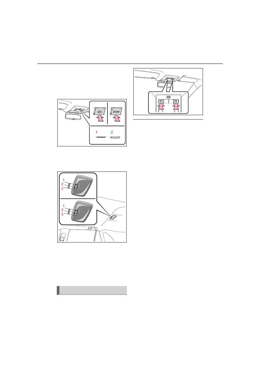
6-2. Using the interior lights
Turns the switch to the door
position (door linked)
When a door is opened while the
door position is on, the lights turn
on.
1
Turns the door position on
2
Turns the lights off
■
Rear interior light
1
Turns the light off
2
Turns the door position on
When a door is opened while the
door position is on, the light turns
on.
3
Turns the light on
Turns the lights on/off
■
Illuminated entry system (vehi-
cles with smart key system)
The lights automatically turn on/off
according to the engine switch
mode, the presence of the elec-
tronic key, whether the doors are
locked/unlocked, and whether the
doors are opened/closed.
■
To prevent the battery from
being discharged
If the interior lights remain on when
the engine switch is turned to OFF,
the lights will go off automatically
after 20 minutes.
■
The interior lights will turn on
automatically when
If any of the SRS airbags deploy
(inflate) or in the event of a strong
rear impact, the interior lights will
turn on automatically.
The interior lights will turn off auto-
matically after approximately 20
minutes.
The interior lights can be turned off
manually. However, in order to help
prevent further collisions, it is rec-
ommended that they be left on until
safety can be ensured.
(The interior lights may not turn on
automatically depending on the
force of the impact and conditions of
the collision.)
■
Customization
Setting (e.g. the time elapsed before
the lights turn off) can be changed.
(Customizable features:
Operating personal lights