Toyota Land Cruiser (2021 year). Manual in english - part 6
336
LC200_OM_OM60T03U_(U)
4-5. Using the driving support systems
●
Switching modes
The display mode switches and the icon display changes each
time the guide line display selection switch is selected.
• Projected course line display mode:
Projected course lines that change according to steering
wheel operations are displayed.
• Parking assist guide line display mode:
Inverted steering wheel operations (parking assist guide line)
are displayed. Use this mode if you are used to how the vehi-
cle handles (if you can park without needing the course line
display).
• Distance guide line display mode:
Only distance guide lines are displayed.
●
Guide lines
The panoramic view & rear view screen is explained here as an
example.
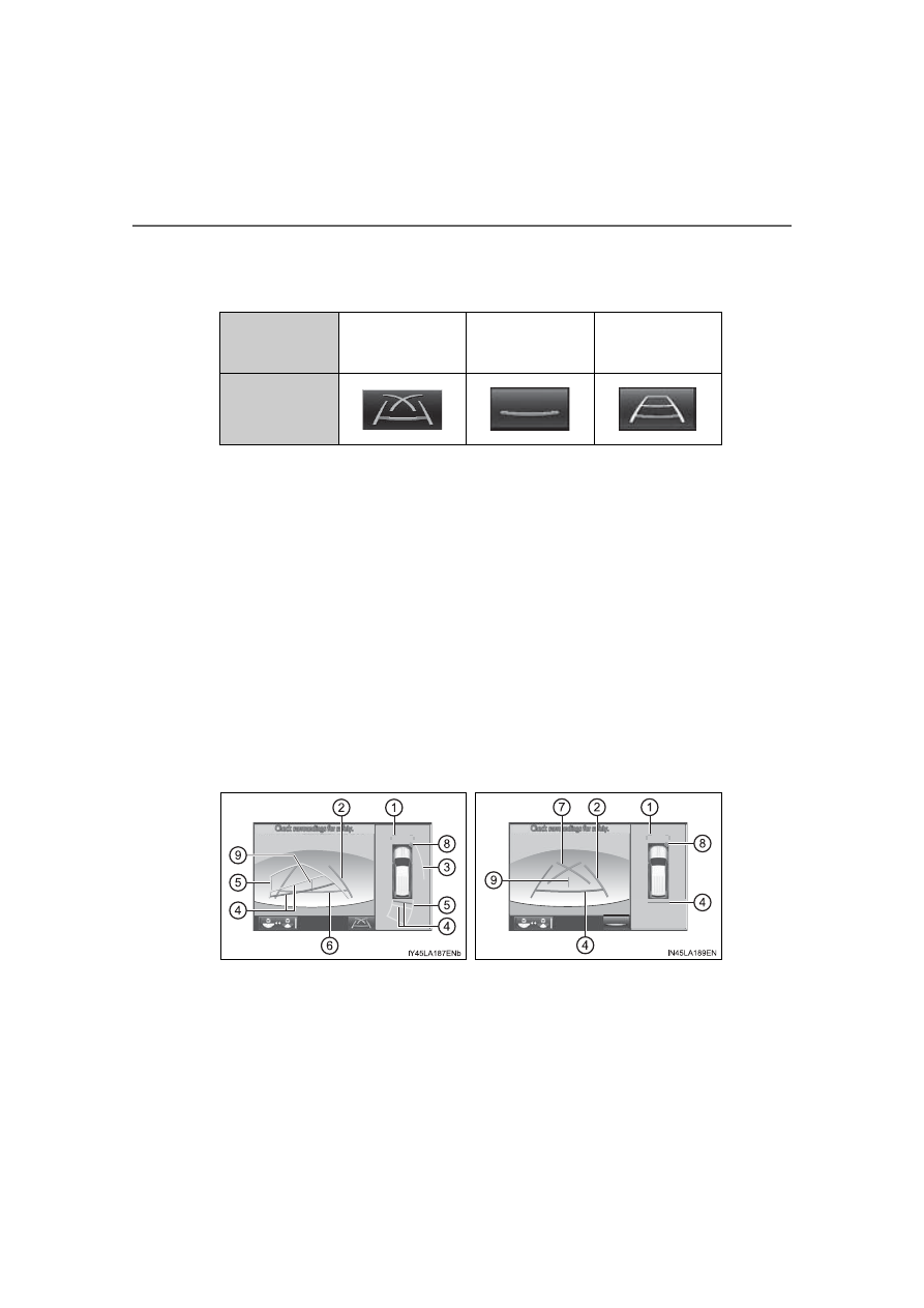
Selected mode
Projected course
line display mode
Parking assist
guide line display
mode
Distance guide
line display mode
Icon display
Projected course line display
mode
Parking assist guide line dis-
play mode