Toyota Automatic Transmission A340 Series. Repair Manual - part 21


  Index      Toyota     Toyota Automatic Transmission A340 Series. Repair Manual


Search            copyright infringement  


Content   ..  19  20  21  22   ..


Toyota Automatic Transmission A340 Series. Repair Manual - part 21


AT5761

AT5797

D5002

No.

Thickness

No.

Thickness

26

3.3 (0.130)

11

3.8 (0.150)

25

3.5 (0.138)

23

3.9 (0.154)

12

3.6 (0.142)

None

4.0 (0.157)

24

3.7 (0.146)

Inside

Outside

Bearing and

race

37.1 (1.461)

59.0 (2.323)

Inside

Outside

Bearing

26.0 (1.024)

46.8 (1.843)

Race

24.2 (0.953)

47.8 (1.882)

Inside

Outside

Race

27.1 (1.067)

41.8 (1.646)

AT5768

mm (in.)

mm (in.)

mm (in.)

HINT: There are seven different thickness for the flange.

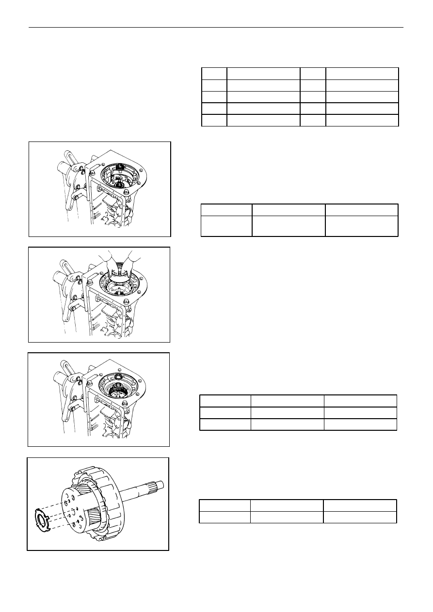
22. INSTALL OVERDRIVE PLANETARY GEAR UNIT

WITH OVERDRIVE DIRECT CLUTCH AND ONE−WAY

CLUTCH
(a)

Coat the assembled bearing and race with petro-

leum jelly and install it onto the overdrive support.

HINT: Assembled bearing and race diameter

(b)

Install the overdrive planetary ring gear.

(c)

Coat the bearing and race with petroleum jelly

and install them onto the planetary ring gear.

HINT: Bearing and race diameter

(d)

Coat the race with petroleum jelly and install it

onto the planetary gear.

HINT: Race diameter

mm (in.)

AUTOMATIC TRANSMISSION (A340F)

Installation of Component Parts

AT−157

AT4470

SST

AT5798

AT8304

Front

AT5799

Inside

Outside

Bearing and

race

28.9 (1.138)

50.2 (1.976)

Inside

Outside

Race

28.1 (1.106)

47.3 (1.862)

AT5759

mm (in.)

(e)

Install the overdrive planetary gear with the over-

drive direct clutch and one−way clutch.

(f)

Place SST on the transmission case.

SST

09350−36010 (09350−06090)

(g)

Using calipers, measure distance between the

tops of SST and the clutch drum.

Standard distance: 15.5 − 16.5 mm (0.610 − 0.650

in.)

If the values are nonstandard, check for an improper

installation.

(h)

Coat the assembled bearing and race with petro-

leum jelly and install it onto the O/D direct clutch.

HINT: Assembled bearing and race diameter

23. INSTALL OIL PUMP INTO CASE

(a)

Coat the race with petroleum jelly and install it

onto the oil pump.

HINT: Race diameter

mm (in.)

(b)

Coat a new O−ring with ATF and install it around

the pump body.

(c)

Place the oil pump through the input shaft, and

align the bolt holes of the pump body with the

transmission case.

(d)

Hold the input shaft, and lightly press the oil pump

body to slide the oil seal rings into the O/D direct

clutch drum.

NOTICE: Do not push on the oil pump strongly, or the

oil seal ring will stick to the direct clutch drum.
(e)

Install the seven bolts.

Torque: 220 kg−cm (16 ft−lb, 22 N−m)

AT−158

AUTOMATIC TRANSMISSION (A340F)

Installation of Component Parts

AT5275

C−1

Accumulator

Piston Hole

AT5751

AT7954

0.4 mm

(0.016 in.)

3 mm (0.12 in.)

A3161

24. CHECK INPUT SHAFT ROTATION

Make sure the input shaft rotates smoothly.

25. INDIVIDUAL PISTON OPERATION INSPECTION

Check for the sound of operation while applying com-

pressed air into the oil hole indicated in the figure.

HINT: When inspecting the O/D direct clutch, check with

the C

0

 accumulator piston hole closed.

If there is no noise, disassemble and check the installa-

tion condition of the parts.

(1)

O/D direct clutch

(2)

Direct clutch

(3)

Forward clutch

(4)

O/D brake

(5)

Second coast brake

(6)

Second brake

(7)

First and reverse brake

26. INSTALL SPEED SENSOR ROTOR AND KEY

(a)

Install the key on the output shaft.

(b)

Align the groove of the sensor rotor with the key,

install the sensor rotor.

(c)

Using snap ring pliers, install the snap ring.

27. INSTALL TRANSFER CASE

(a)

Clean contacting surface of any residual packing

material using gasoline alcohol.

(b)

Apply seal packing to the case as shown in the fig-

ure.

Seal packing:  Part No. 08826 − 00090, THREE BOND

 1281 or equivalent

AUTOMATIC TRANSMISSION (A340F)

Installation of Component Parts

AT−159

AT5238

SST

AT5405

AT5105

AT4465 D5048

40 (1.57)

mm (in.)

50 (1.97)

AT5889

(c)

Install the case and torque the seven bolts.

Torque: 345 kg−cm (25 ft−lb, 34 N−m)

HINT: Each bolt length (mm, in.) is indicated in the figure.

28. INSTALL MANUAL VALVE LEVER, SHAFT AND OIL

SEALS
(a)

Using SST, drive in two new oil seals.

SST

09350−30020 (09350−07110)

(b)

Coat the oil seal lip with MP grease.

(c)

Install a new spacer to the manual valve lever.

(d)

Install the manual valve lever shaft to the trans-

mission case through the manual valve lever.

(e)

Using a hammer, drive in a new spring pin.

(f)

Match the manual valve lever indentation with the

spacer hole and caulk them th the punch.

(g)

Make sure the shaft rotates smoothly.

AT−160

AUTOMATIC TRANSMISSION (A340F)

Installation of Component Parts

AT5406

AT8240

AT5241

AT5800

D5035

Lock Pawl

E−Ring

Pin

Spring

29. INSTALL PARKING LOCK PAWL AND ROD

(a)

Install the E−ring to the shaft.

(b)

Install the parking lock pawl, shaft and spring.

(c)

Connect the parking lock rod to the manual valve

lever.

(d)

Place the parking lock pawl bracket onto the

transmission case and torque the three bolts.

Torque: 75 kg−cm (65 in.−lb, 7 N−m)

(e)

Shift the manual valve lever to the P position, and

confirm the planetary ring gear is correctly locked

up by the lock pawl.

34. INSTALL ACCUMULATOR SPRINGS AND PISTONS

(a)

Coat new O−rings with ATF and install them to the

pistons.

(b)

Install the four springs and pistons to the bore as

shown in the figure.

AUTOMATIC TRANSMISSION (A340F)

Installation of Component Parts

AT−161

AT4847

Check Ball

Body

E7074

E7256

Throttle Cable

Cam

AT7491

23 (0.91)

23 (0.91)

32 (1.26)

32

(1.26)

32 (1.26)

23 (0.91) 32 (1.26)

mm (in.)

Spring

Free length

Outer diameter

Color

(1)

B

2

70.5 (2.776)

19.7 (0.776)

Yellow

(2)

C

2

68.5 (2.698)

20.2 (0.795)

Blue

(4)

B

0

69.7 (2.744)

16.7 (0.657)

Light

Green

(5)

C

0

67.0 (2.638)

17.8 (0.701)

White

AT5801

mm (in.)

HINT: The pistons are marked in relief with either C−0,

B−0, C−2, B−2 to differentiate between them.

31. INSTALL CHECK BALL BODY AND SPRING

32. INSTALL THROTTLE CABLE

(a)

Coat a new O−ring with ATF and install it to the

cable.

(b)

Install the cable to the case.

33. INSTALL VALVE BODY

(a)

Align the groove of the manual valve to the pin of

the lever.

(b)

Connect the throttle cable to the cam.

(c)

Confirm the springs into the accumulator pistons

are installed correctly.

(d)

Install the sixteen bolts.

HINT: Each bolt length (mm, in.) is indicated in the figure.

Torque: 100 kg−cm (7 ft−lb, 10 N−m)

AT−162

AUTOMATIC TRANSMISSION (A340F)

Installation of Component Parts

AT1354

AT5754

AT5802

AT7910

AT5066

34. INSTALL TRANSMISSION SOLENOID WIRING

(a)

Coat a new O−ring with ATF and install it to the

grommet.

(b)

Insert the solenoid wiring to the case and install

the stopper plate.

(c)

Connect the connectors to No. 1, No. 2 and lock−up

solenoids.

35. INSTALL OIL TUBE

Using a plastic hammer, install the tube into position

shown in the figure.

NOTICE: Be careful not to bend or damage the tube.

36. INSTALL OIL STRAINER AND GASKETS

(a)

Install two new gaskets to the oil strainer case.

(b)

Install the oil strainer case and torque the five bolts.

Torque: 100 kg−cm (7 ft−lb, 10 N−m)

HINT: Each bolt length (mm, in.) is indicated in the figure.

AUTOMATIC TRANSMISSION (A340F)

Installation of Component Parts

AT−163

AT7909

mm (in.)

246 (9.69)

72

(2.83)

82 (3.23)

10 (0.39)

5 (0.20)

10 (0.39)

52 (2.05)

30 (1.18)

30 (1.18) 67 (2.64)

E7058

TF0638

AT1362

2 − 3 mm (0.08 − 0.12 in.)

AT5803

(c)

Install a new gasket to the oil strainer case.

(d)

Install the oil strainer and torque the eleven bolts.

Torque: 70 kg−cm (61 in.−lb, 6.9 N−m)

37. INSTALL OIL PAN

(a)

Install the six magnets as shown in the figure.

(b)

Remove any packing material and be careful not to

drop oil on the contacting surfaces of the transmis-

sion case and oil pan.

(c)

Apply seal packing to the oil pan as shown in the

figure.

Seal packing:  Part No. 08826 − 00090, THREE BOND

1281 or equivalent

(d)

Install and torque the nineteen bolts.

Torque: 75 kg−cm (65 in.−lb, 7.4 N−m)

38. INSTALL TRANSFER AND PROPELLER SHAFT UP-

PER DUST COVER TO TRANSMISSION WITH NEW

GASKET
(a)

Shift the two shift fork shafts to the high−four

position.

AT−164

AUTOMATIC TRANSMISSION (A340F)

Installation of Component Parts


Content   ..  19  20  21  22   ..