Toyota Automatic Transmission A340 Series. Repair Manual - part 20
AT5785
AT5776
AT5786
SST
AT8223
AT7893
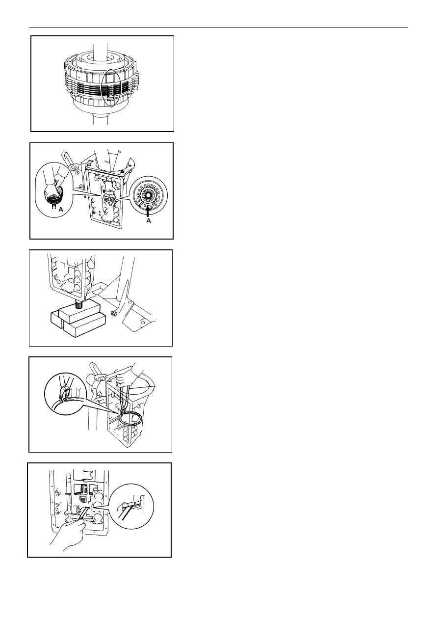
(f)
Align the teeth of the second brake drum, flange,
discs and plates as shown in the figure.
(g)
Align the splines of the transmission case and the
assembled rear planetary gear, second brake
drum, first and reverse brake pack and output
shaft, indicated by A.
(h)
Hold the output shaft with wooden blocks or
equivalents.
(i)
Using SST, install the snap ring.
SST
09350−30020 (09350−07060)
5.
CHECK PACK CLEARANCE OF FIRST AND REVERSE
BRAKE
Using a feeler gauge, measure the clearance between
the plate and second brake drum as shown in the figure.
Clearance: 0.50 − 1.02 mm (0.0197 − 0.0402 in.)
If the values are nonstandard, select another flange.
−
AUTOMATIC TRANSMISSION (A340F)
Installation of Component Parts
AT−149