Toyota FJ Cruiser (GSJ 10, 15 series). Instruction - part 54
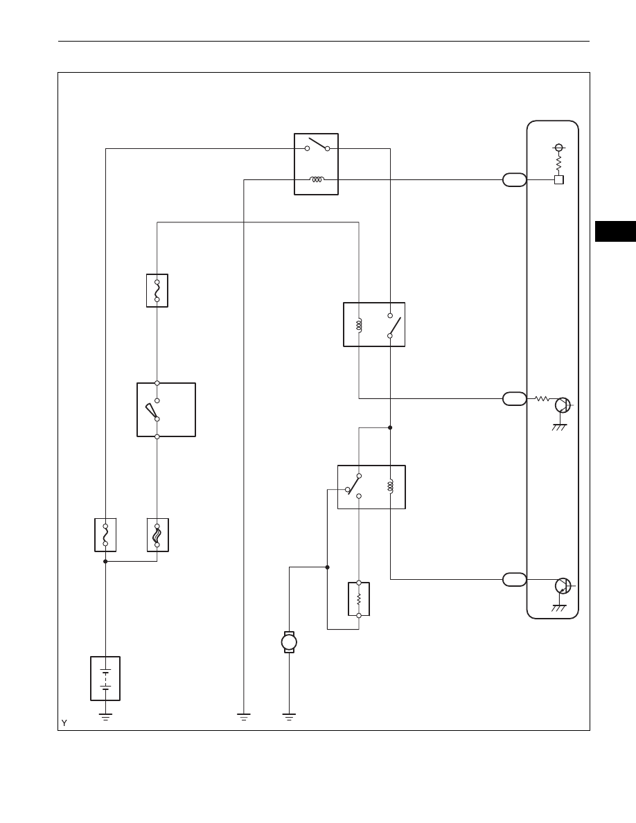
1GR-FE ENGINE CONTROL SYSTEM – SFI SYSTEM
ES–171
ES
WIRING DIAGRAM
M
Battery
AM2
EFI
AM2
IG2
IGN
Ignition Switch
EFI
ECM
MREL
C/OPN
Fuel Pump Resistor
FC
FPR
Fuel Pump
FUEL PUMP
1
3
2
5
1
3
2
5
3
1
5
2
4
1
2
4
5
L5
A13
30
B3
10
E47
8
E47
A1
6
7
2
1
2
1
A133414E02