Toyota FJ Cruiser (GSJ 10, 15 series). Instruction - part 53


  Index      Toyota     Toyota FJ Cruiser (model GSJ 10, 15 series) - service repair instruction 2007 year


Search            copyright infringement  


Content   ..  51  52  53  54   ..


Toyota FJ Cruiser (GSJ 10, 15 series). Instruction - part 53


1GR-FE ENGINE CONTROL SYSTEM  –  SFI SYSTEM

ES–167

ES

(a) Connect an intelligent tester to the DLC3.
(b) Turn the ignition switch ON and turn the tester ON.
(c) Clear DTCs (See page 

ES-38

).

(d) Switch the ECM from normal mode to check mode using 
the tester (See page 

ES-42

).

(e) Start the engine and warm it up with all the accessories 
switched OFF.
(f) Drive the vehicle at between 38 mph and 75 mph (60 km/h 
and 120 km/h) and at an engine speed of between 1,400 rpm 
and 3,200 rpm for 3 to 5 minutes.
HINT:
If the system is still malfunctioning, the MIL will be illuminated 
during step (f).
NOTICE:
If the conditions in this test are not strictly followed, no 
malfunction will be detected.

NEXT

(a) Connect an intelligent tester to the DLC3.
(b) Turn the ignition switch ON and turn the tester ON.
(c) Select the following menu items: DIAGNOSIS / 

ENHANCED OBD II / DTC INFO / CURRENT CODES.

(d) Read DTCS.

15

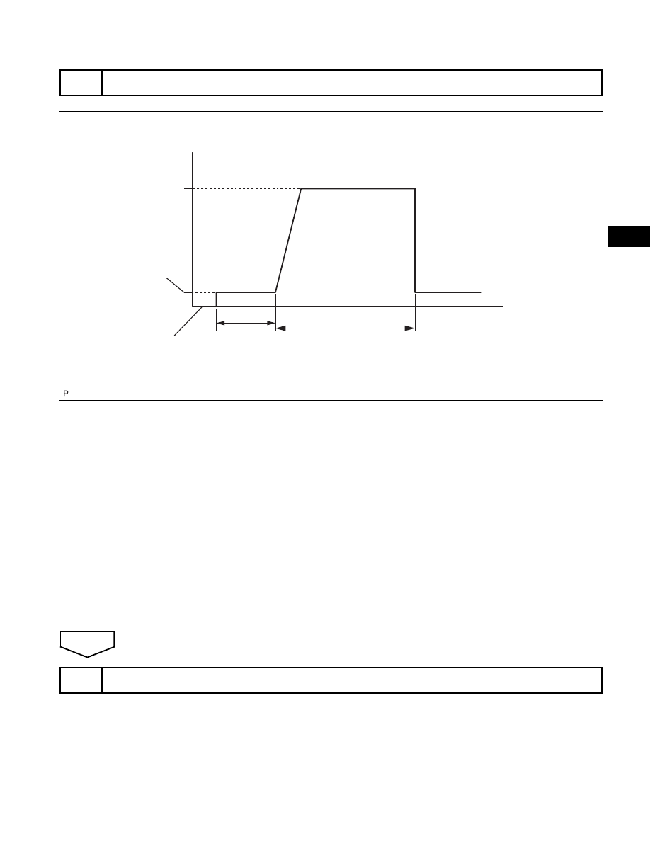
PERFORM CONFIRMATION DRIVING PATTERN

Ignition Switch OFF

Idling

Between

38 and 75 mph 
(60 and 120 km/h)

Vehicle Speed

(e)

(f)

Warming up

3 to 5 minutes

Time

(a), (b), (c), (d)

A115372E10

16

CHECK WHETHER DTC OUTPUT RECURS (DTC P0171, P0172, P0174 OR P0175)

ES–168

1GR-FE ENGINE CONTROL SYSTEM  –  SFI SYSTEM

ES

Result

B

A

Display (DTC Output)

Proceed To

No output

A

P0171, P0172, P0174 or P0175

B

              Go to step 5

END

1GR-FE ENGINE CONTROL SYSTEM  –  SFI SYSTEM

ES–169

ES

DESCRIPTION

As shown in the illustration, when the engine is cranked, current flows from terminal ST1 of the ignition 
switch into the ECM and the ST (starter) relay coil and also current flows to terminal STA of the ECM (STA 
signal).
When the STA signal and NE signal are input to the ECM, Tr1 (power transistor 1) is turned ON, current 
flows to the coil of the circuit opening relay, the relay switches on, power is supplied to the fuel pump, and 
the fuel pump operates.
While the NE signal is generated (engine running), the ECM keeps the Tr1 ON (circuit opening relay ON) 
and the fuel pump also keeps operating.
The fuel pump speed is controlled at two levels (high speed or low speed) by engine condition (starting, 
light load, heavy load). When the engine starts (STA ON), Tr2 (power transistor 2) in the ECM is OFF, so 
the fuel pump relay closes and positive battery voltage is applied directly to the fuel pump. The fuel pump 
operates at high speed.
During idling or under light loads, Tr2 goes ON, and then power is supplied to the fuel pump via the fuel 
pump resistor. The fuel pump operates at low speed.

DTC

P0230

Fuel Pump Primary Circuit

ES–170

1GR-FE ENGINE CONTROL SYSTEM  –  SFI SYSTEM

ES

DTC No.

DTC Detection Conditions

Trouble Areas

P0230

Open or short in fuel pump relay circuit
(1 trip detection logic)

Open or short in fuel pump relay circuit

Fuel pump relay

ECM

IG1

ST1

Battery

Starter

STA

IG2

ST2

ALT

AM2

AM1

AM1

AM2

STA

IGN

C/OPN

EFI

EFI

STA

NE

FC

FPR

MREL

Tr1

Tr2

ECM

Fuel Pump Resistor

FUEL PUMP

Fuel Pump

Clutch 
Start 
Switch

Park/Neutral 
Position 
Switch

Ignition Switch

*1

Crankshaft Position 
Sensor (NE Signal)

*2: For Manual Transmission

*1: For Automatic Transmission

*1

*2

*2

*2

A133413E01


Content   ..  51  52  53  54   ..