Toyota Tundra (2015 year). Manual - part 975


  Index      Toyota     Toyota Tundra (2015 year) - Service and Repair Manual


Search            copyright infringement  


Content   ..  973  974  975  976   ..


Toyota Tundra (2015 year). Manual - part 975


A

The vehicle is equipped with an SRS (Supplemental Restraint System) which includes components such as


.

PROCEDURE

1.

CHECK ILLUMINATION

(a) Check if the illumination for the radio and display receiver assembly, steering pad switch assembly,

glove box or other parts (hazard switch, transmission control switch, etc.) comes on when the light
control switch is turned to the head or tail position.

Result

RESULT

PROCEED

TO

Illumination comes on for all components except steering pad switch assembly

A

Illumination comes on for all components except radio and display receiver assembly

B

No illumination comes on (radio and display receiver assembly, hazard switch, glove box, etc.)

C

Illumination comes on for all components except steering pad switch assembly and radio and

display receiver assembly

D

B

GO TO STEP 6

C

GO TO LIGHTING SYSTEM

D

GO TO STEP 7

2.

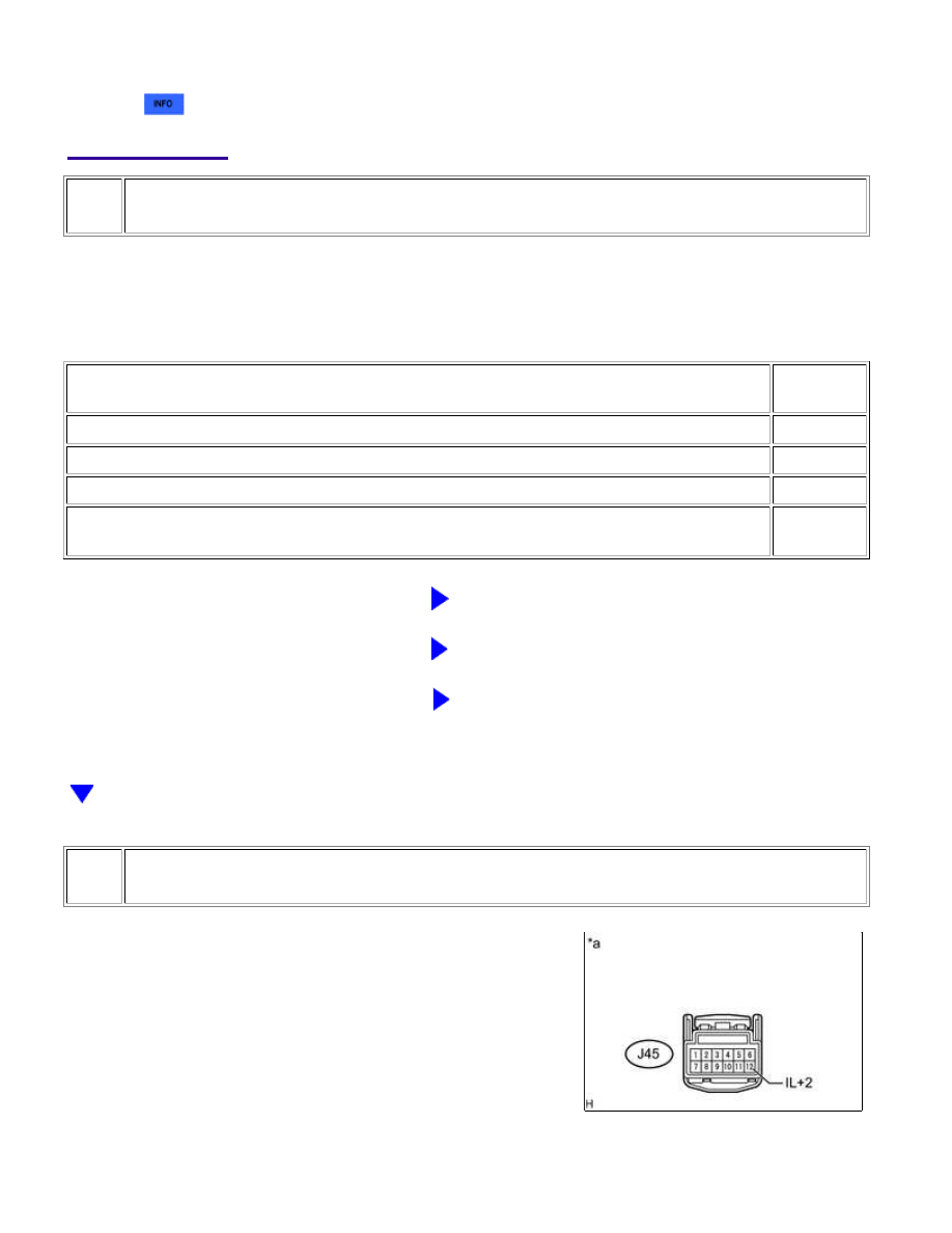
CHECK HARNESS AND CONNECTOR (SPIRAL CABLE SUB-ASSEMBLY - BATTERY)

(a) Disconnect the spiral cable sub-assembly connector.

(b) Measure the voltage according to the value(s) in the table below.

AUDIO / VISUAL: AUDIO AND VISUAL SYSTEM: Illumination Circ...

OK

OK

OK

Standard Voltage:

TESTER CONNECTION

SWITCH CONDITION

SPECIFIED CONDITION

J45-12 (IL+2) - Body ground Headlight dimmer switch assembly tail or head position

11 to 14 V

Text in Illustration

*a

NG

REPAIR OR REPLACE HARNESS OR CONNECTOR

3.

INSPECT STEERING PAD SWITCH ASSEMBLY

(a) Remove the steering pad switch assembly 


.

(b) Inspect the steering pad switch assembly 


.

NG

REPLACE STEERING PAD SWITCH ASSEMBLY

4.

INSPECT SPIRAL CABLE SUB-ASSEMBLY

(a) Remove the spiral cable sub-assembly 


.

(b) Inspect the spiral cable sub-assembly 


.

NG

REPLACE SPIRAL CABLE SUB-ASSEMBLY

5.

CHECK HARNESS AND CONNECTOR (RADIO AND DISPLAY RECEIVER ASSEMBLY -
SPIRAL CABLE SUB-ASSEMBLY)

AUDIO / VISUAL: AUDIO AND VISUAL SYSTEM: Illumination Circ...

(a) Disconnect the J139 radio and display receiver assembly connector.

(b) Disconnect the J45 spiral cable sub-assembly connector.

(c) Measure the resistance according to the value(s) in the table below.

Standard Resistance:

TESTER CONNECTION

CONDITION

SPECIFIED CONDITION

J139-23 (SWG) - J45-3 (EAU)

Always

Below 1 Ω

J139-23 (SWG) - Body ground

Always

10 kΩ or higher

NG

REPAIR OR REPLACE HARNESS OR CONNECTOR

OK

PROCEED TO NEXT SUSPECTED AREA SHOWN IN

PROBLEM SYMPTOMS TABLE

6.

CHECK HARNESS AND CONNECTOR (RADIO AND DISPLAY RECEIVER ASSEMBLY -
BATTERY)

(a) Disconnect the radio and display receiver assembly connector.

(b) Measure the voltage according to the value(s) in the table below.

Standard Voltage:

TESTER CONNECTION

SWITCH CONDITION

SPECIFIED CONDITION

J137-10 (ILL+) - Body ground Headlight dimmer switch assembly tail or head position 11 to 14 V

Text in Illustration

*a

NG

REPAIR OR REPLACE HARNESS OR CONNECTOR

OK

PROCEED TO NEXT SUSPECTED AREA SHOWN IN

PROBLEM SYMPTOMS TABLE

AUDIO / VISUAL: AUDIO AND VISUAL SYSTEM: Illumination Circ...

7.

CHECK HARNESS AND CONNECTOR (RADIO AND DISPLAY RECEIVER ASSEMBLY -
COMBINATION METER ASSEMBLY)

(a) Disconnect the J138 radio and display receiver assembly connector.

(b) Disconnect the J28 combination meter assembly connector.

(c) Measure the resistance according to the value(s) in the table below.

Standard Resistance:

TESTER CONNECTION

CONDITION

SPECIFIED CONDITION

J138-5 (ILL-) - J28-22 (ILL-)

Always

Below 1 Ω

J138-5 (ILL-) - Body ground

Always

10 kΩ or higher

NG

REPAIR OR REPLACE HARNESS OR CONNECTOR

OK

PROCEED TO NEXT SUSPECTED AREA SHOWN IN

PROBLEM SYMPTOMS TABLE

AUDIO / VISUAL: AUDIO AND VISUAL SYSTEM: Illumination Circ...


Content   ..  973  974  975  976   ..