Toyota Tundra (2015 year). Manual - part 768
5. CHECK SHIFT LOCK CONTROL ECU (for Floor Shift Type)
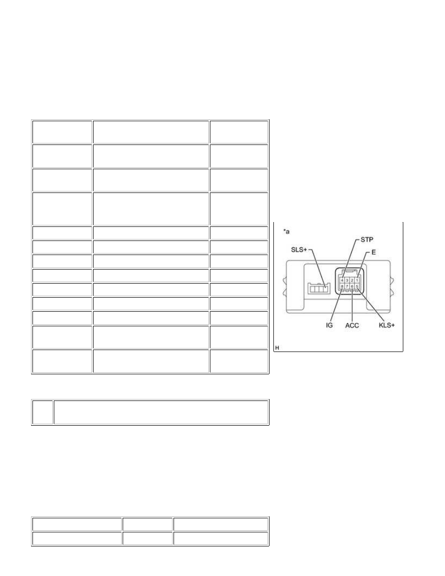
(a) Measure the voltage according to the value(s) in the table
below.
HINT:
TESTER
CONNECTION
CONDITION
SPECIFIED
CONDITION
5 (KLS+) - 1 (E)
Ignition switch ACC and shift
lever in P
Below 1 V
5 (KLS+) - 1 (E)
Ignition switch ACC and shift
lever not in P
7.5 to 11 V
5 (KLS+) - 1 (E)
Ignition switch ACC and shift
lever not in P (after approx. 1
second)
6 to 9 V
6 (ACC) - 1 (E)
Ignition switch ON
10 to 14 V
6 (ACC) - 1 (E)
Ignition switch ACC
10 to 14 V
6 (ACC) - 1 (E)
Ignition switch off
Below 1 V
4 (STP) - 1 (E)
Brake pedal depressed
10 to 14 V
4 (STP) - 1 (E)
Brake pedal released
Below 1 V
8 (IG) - 1 (E)
Ignition switch ON
10 to 14 V
8 (IG) - 1 (E)
Ignition switch off
Below 1 V
SLS+ - 1 (E)
Ignition switch ON and brake
pedal depressed
10 to 14 V
SLS+ - 1 (E)
Ignition switch ON and brake
pedal released
Below 1 V
Text in Illustration
*a
Component with harness connected
(Shift Lock Control ECU)
If the result is not as specified, replace the shift lock control ECU.
(b) Measure the resistance according to the value(s) in the table
below.
NOTICE:
Do not disconnect the shift lock control ECU connector.
Standard Resistance:
TESTER CONNECTION
CONDITION
SPECIFIED CONDITION
1 (E) - Body ground
Always
Below 1 Ω
AB60F AUTOMATIC TRANSMISSION: SHIFT LOCK SYSTEM: O...