Toyota Tundra (2015 year). Manual - part 765


  Index      Toyota     Toyota Tundra (2015 year) - Service and Repair Manual


Search            copyright infringement  


Content   ..  763  764  765  766   ..


Toyota Tundra (2015 year). Manual - part 765


Last Modified: 9-16-2014

6.6 A

Doc ID: RM000002YBG03UX

Model Year: 2015

Model: Tundra

Prod Date Range: [08/2014 -           ]

Title: AB60F AUTOMATIC TRANSMISSION: SHIFT LEVER ASSEMBLY (for Floor Shift Type): DISASSEMBLY; 2015

MY Tundra [08/2014 -        ]

DISASSEMBLY

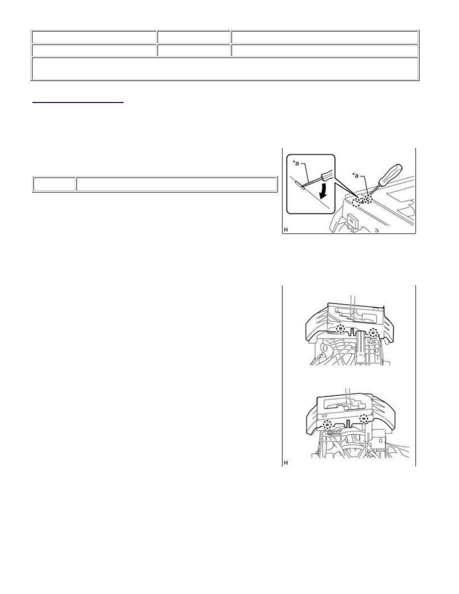
1. REMOVE SHIFT LEVER CAP

(a) Using a screwdriver, detach the 2 claws and remove the shift

lever cap from the upper position indicator housing.

Text in Illustration

*a

Protective Tape

NOTICE:

Be careful not to damage the shift lever cap.

HINT:

Tape the screwdriver tip before use.

2. REMOVE UPPER POSITION INDICATOR HOUSING

(a) Detach the 4 claws and remove the upper position indicator

housing from the shift lever assembly.

3. REMOVE POSITION INDICATOR SLIDE COVER

AB60F AUTOMATIC TRANSMISSION: SHIFT LEVER ASSEMBLY ...

(a) Remove the position indicator slide cover together with the No.

2 position indicator slide cover from the shift lever assembly.

4. REMOVE NO. 2 POSITION INDICATOR SLIDE COVER

(a) Remove the No. 2 position indicator slide cover from the

position indicator slide cover.

5. DISCONNECT INDICATOR LIGHT WIRE SUB-ASSEMBLY

(a) Using a thin-bladed screwdriver, release the connector housing

retainer.

Text in Illustration

*1

Connector Housing Retainer

*a

Component without harness connected

(Transmission Control Switch)

(b) Using a thin-bladed screwdriver, pull out the 4 (ILL+) and 8 (ILL-) terminals from the rear as shown in the

illustration.

AB60F AUTOMATIC TRANSMISSION: SHIFT LEVER ASSEMBLY ...

(c) Detach the 4 guides from the shift lever assembly.

6. REMOVE LOWER POSITION INDICATOR HOUSING

(a) Using a small screwdriver, detach the 4 claws and remove the

lower position indicator housing from the shift lever assembly.

Text in Illustration

*a

Protective Tape

NOTICE:

Be careful not to damage the lower position indicator housing

and shift lever assembly.

HINT:

Tape the screwdriver tip before use.

7. REMOVE INDICATOR LIGHT WIRE SUB-ASSEMBLY

(a) Disconnect the connector and remove the indicator light wire

sub-assembly from the lower position indicator housing.

8. REMOVE POSITION INDICATOR LED

AB60F AUTOMATIC TRANSMISSION: SHIFT LEVER ASSEMBLY ...

(a) Detach the claw and remove the position indicator LED from the

lower position indicator housing.

9. REMOVE SHIFT LOCK CONTROL ECU

(a) Disconnect the shift lock solenoid connector.

(b) Detach the 3 claws and remove the shift lock control ECU from the shift lever assembly.

AB60F AUTOMATIC TRANSMISSION: SHIFT LEVER ASSEMBLY ...


Content   ..  763  764  765  766   ..