Toyota Tundra (2015 year). Manual - part 688
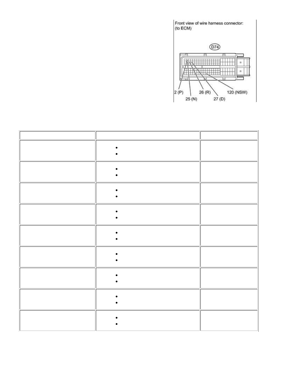
(a) Disconnect the D74 ECM connector.
(b) Measure the voltage according to the value(s) in the table below.
Standard voltage:
TESTER CONNECTION
CONDITION
SPECIFIED CONDITION
D74-2 (P) - Body ground
Ignition switch ON
Shift lever position on P
11 to 14 V
D74-26 (R) - Body ground
Ignition switch ON
Shift lever position on R
11 to 14 V*
D74-25 (N) - Body ground
Ignition switch ON
Shift lever position on N
11 to 14 V
D74-27 (D) - Body ground
Ignition switch ON
Shift lever position on D
11 to 14 V
D74-120 (NSW) - Body ground
Ignition switch ON
Shift lever position not on P or N
11 to 14 V
D74-2 (P) - Body ground
Ignition switch ON
Shift lever position not on P
Below 1 V
D74-26 (R) - Body ground
Ignition switch ON
Shift lever position not on R
Below 1 V
D74-25 (N) - Body ground
Ignition switch ON
Shift lever position not on N
Below 1 V
D74-27 (D) - Body ground
Ignition switch ON
Shift lever position not on D
Below 1 V
AB60F AUTOMATIC TRANSMISSION: AUTOMATIC TRANSMIS...