Toyota Tundra (2015 year). Manual - part 634


  Index      Toyota     Toyota Tundra (2015 year) - Service and Repair Manual


Search            copyright infringement  


Content   ..  632  633  634  635   ..


Toyota Tundra (2015 year). Manual - part 634


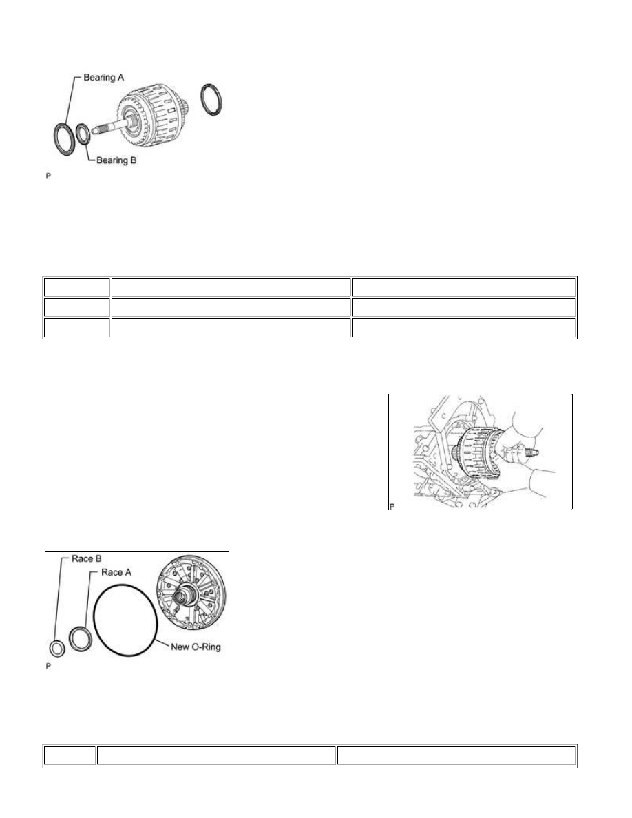
52. INSTALL CLUTCH DRUM AND INPUT SHAFT ASSEMBLY

(a) Install the 2 thrust needle roller bearings.

HINT:

ITEM

INSIDE

OUTSIDE

Bearing A

72.0 to 72.3 mm (2.83 to 2.85 in.)

85.3 to 85.6 mm (3.36 to 3.37 in.)

Bearing B

36.5 to 36.7 mm (1.437 to 1.445 in.)

52.9 to 53.2 mm (2.08 to 2.09 in.)

(b) Coat the clutch drum thrust washer with MP grease and install it to the clutch drum and input shaft

assembly.

(c) Install the clutch drum and input shaft drum assembly onto the

transmission case.

53. INSTALL OIL PUMP ASSEMBLY

(a) Coat a new O-ring with ATF, and install it to the oil pump.

(b) Install the 2 thrust bearing races to the front oil pump.

Thrust bearing race diameter:

ITEM

INSIDE

OUTSIDE

AB60E AUTOMATIC TRANSMISSION: AUTOMATIC TRANSMIS...

ITEM

INSIDE

OUTSIDE

Race A

74.3 to 74.6 mm (2.93 to 2.94 in.)

87.4 to 87.7 mm (3.44 to 3.45 in.)

Race B

38.0 to 38.3 mm (1.50 to 1.51 in.)

53.9 to 54.1 mm (2.12 to 2.13 in.)

transmission case.

(d) Hold the input shaft, and lightly press the oil pump body to slide the oil seal rings into the overdrive direct

clutch drum.

Toyota Genuine Seal Packing 1281, Three Bond 1281 or equivalent

NOTICE:

Do not allow seal packing to contact the bolts' threads.

(f) Install the 10 bolts.

Torque:

21 N·m {214 kgf·cm, 15ft·lbf}

NOTICE:

55. INSTALL MANUAL VALVE LEVER SHAFT OIL SEAL

(a) Using SST, tap in 2 new oil seals.

SST: 09350-30020

09350-07110

AB60E AUTOMATIC TRANSMISSION: AUTOMATIC TRANSMIS...

(a) Install a new spacer to the manual valve lever.

(b) Push the manual valve lever shaft through the transmission case, and install the manual valve lever to the

shaft.

(c) Using a hammer, tap in a new spring pin.

(d) Align the manual valve lever indentation with the spacer hole,

and stake them together with the punch.

(e) Check that the shaft rotates smoothly.

57. INSTALL PARKING LOCK PAWL

(a) Install a new E-ring to the shaft.

(b) Install the parking lock pawl, shaft and spring.

AB60E AUTOMATIC TRANSMISSION: AUTOMATIC TRANSMIS...

58. INSTALL PARKING LOCK ROD SUB-ASSEMBLY

(a) Connect the parking lock rod to the manual valve lever.

59. INSTALL PARKING LOCK PAWL BRACKET

(a) Place the parking lock pawl bracket onto the transmission case and install the 3 bolts.

Torque:

18 N·m {184 kgf·cm, 13ft·lbf}

(b) Move the manual valve lever to the P position, and confirm that

the planetary ring gear is correctly locked by the lock pawl.

60. INSTALL B-1 ACCUMULATOR VALVE

(a) Install the 2 springs and accumulator valve to the hole.

Spring diameter:

SPRING

FREE LENGTH

OUTER DIAMETER

COLOR

B-1 Inner

44.98 mm (1.77 in.)

11.30 mm (0.445 in.)

Natural

B-1 Outer

46.36 mm (1.83 in.)

17.10 mm (0.673 in.)

Natural

AB60E AUTOMATIC TRANSMISSION: AUTOMATIC TRANSMIS...


Content   ..  632  633  634  635   ..