Toyota Tundra (2015 year). Manual - part 433
Last Modified: 9-16-2014
6.6 U
Doc ID: RM000000W740LMX
Model Year: 2015
Model: Tundra
Prod Date Range: [08/2014 - ]
Title: A760F AUTOMATIC TRANSMISSION: AUTOMATIC TRANSMISSION SYSTEM: TERMINALS OF ECM; 2015
MY Tundra [08/2014 - ]
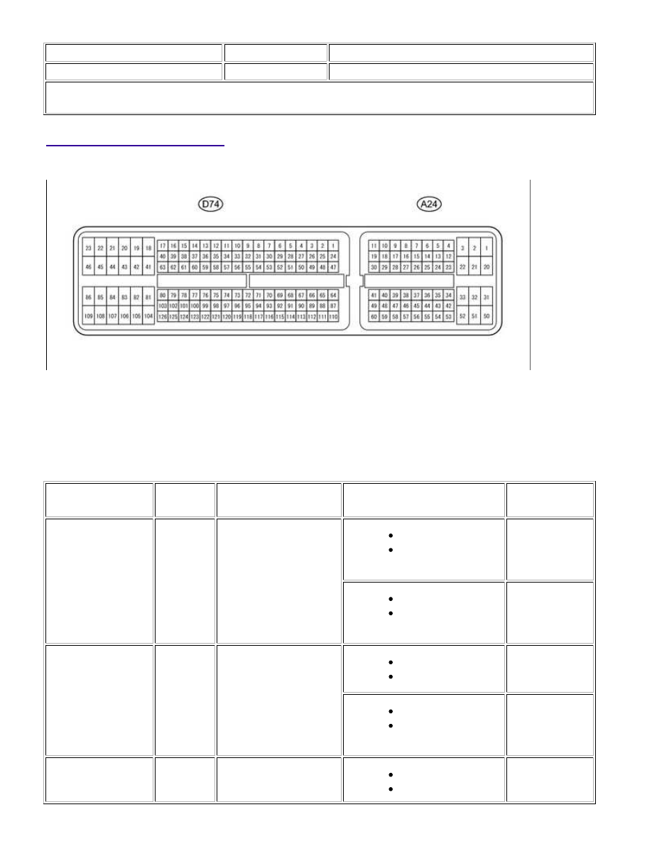
TERMINALS OF ECM
1. CHECK ECM
HINT:
The standard voltage at each ECM terminal is shown in the table below.
In the table, first follow the information under "Condition". Look under "Terminal No. (Symbol)" for the
terminals to inspect. The standard voltage between the terminals is shown under "Specified Condition".
Use the illustration above as a reference for the ECM terminals.
TERMINAL NO.
(SYMBOL)
WIRING
COLOR
TERMINAL
DESCRIPTION
CONDITION
SPECIFIED
CONDITION
A24-21 (L4) -
D74-81 (E1)
G - BR
4L position signal
Ignition switch ON
Transfer position
switch on 4L
Below 1.5 V
Ignition switch ON
Transfer position
switch not on 4L
11 to 14 V
D74-120 (NSW) -
D74-81 (E1)
L - BR
PNP switch signal
Ignition switch ON
Shift lever in P or N
Below 1 V
Ignition switch ON
Shift lever not in P or
N
11 to 14 V
D74-2 (P) - D74-81
(E1)
G-B - BR
P shift position switch
signal
Ignition switch ON
Shift lever in P
11 to 14 V
A760F AUTOMATIC TRANSMISSION: AUTOMATIC TRANSMISS...