Toyota Tundra (2015 year). Manual - part 272
Last Modified: 9-16-2014
6.6 J
Doc ID: RM000000XG602QX
Model Year: 2015
Model: Tundra
Prod Date Range: [08/2014 - ]
Title: BRAKE CONTROL: VEHICLE STABILITY CONTROL SYSTEM: TC and CG Terminal Circuit; 2015 MY Tundra
[08/2014 - ]
TC and CG Terminal Circuit
DESCRIPTION
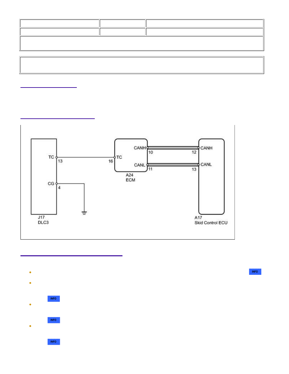
WIRING DIAGRAM
INSPECTION PROCEDURE
NOTICE:
.
for 3UR-FE:
If the ECM has been replaced, it is necessary to register the Vehicle Identification Number (VIN)
.
for 3UR-FBE:
If the ECM has been replaced, it is necessary to register the Vehicle Identification Number (VIN)
.
BRAKE CONTROL: VEHICLE STABILITY CONTROL SYSTEM: T...