Toyota Tundra (2015 year). Manual - part 2670


  Index      Toyota     Toyota Tundra (2015 year) - Service and Repair Manual


Search            copyright infringement  


Content   ..  2668  2669  2670  2671   ..


Toyota Tundra (2015 year). Manual - part 2670


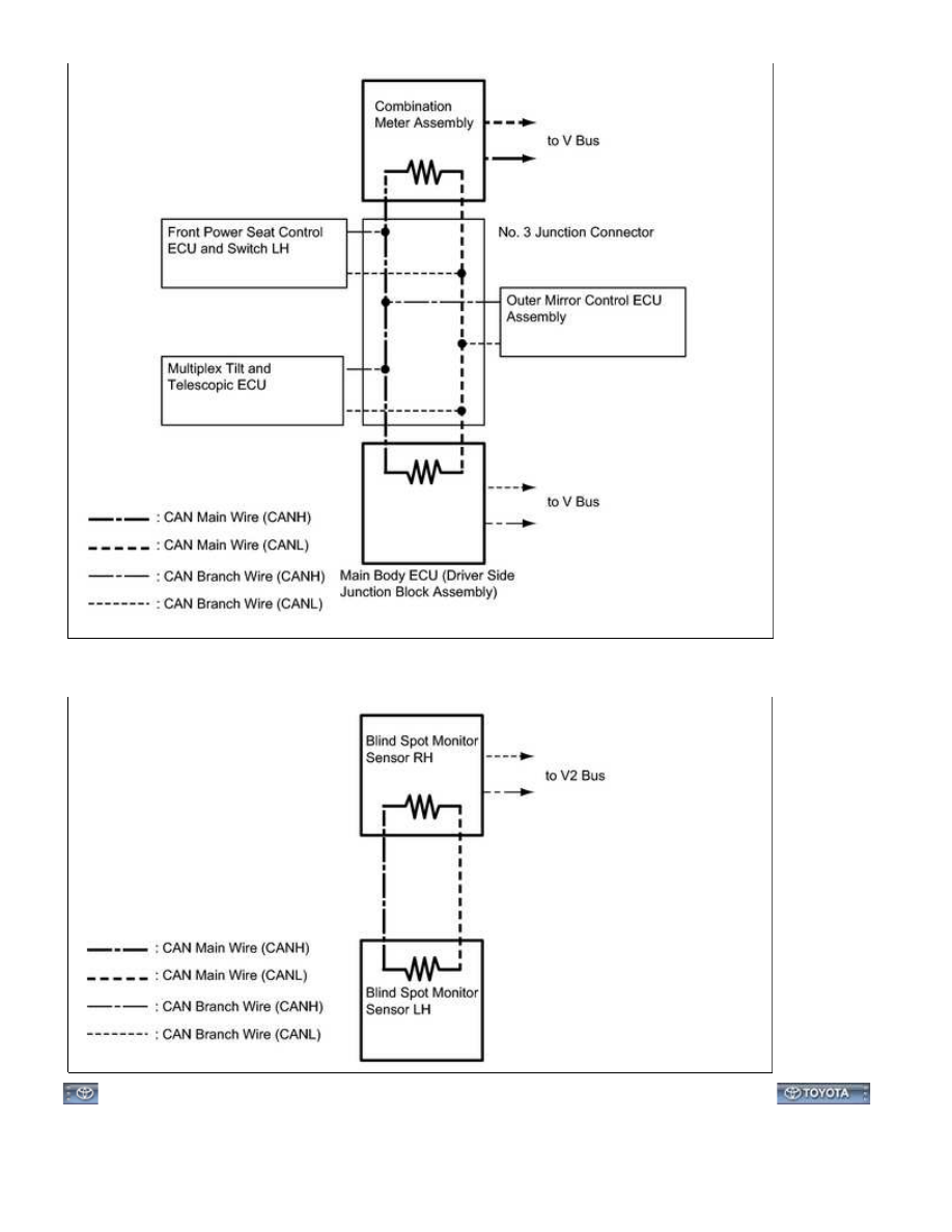
5. SENSOR BUS (w/ Blind Spot Monitor System)

CAN COMMUNICATION: CAN COMMUNICATION SYSTEM: SYST...

Last Modified: 9-16-2014

6.6 D

Doc ID: RM000004G1M00FX

Model Year: 2015

Model: Tundra

Prod Date Range: [08/2014 -           ]

Title: CAN COMMUNICATION: CAN COMMUNICATION SYSTEM: SYSTEM DESCRIPTION; 2015 MY Tundra

[08/2014 -        ]

SYSTEM DESCRIPTION

1. BRIEF DESCRIPTION

(a) The CAN (Controller Area Network) is a serial data communication system for real-time application. It is a

vehicle multiplex communication system which has a high communication speed (500 kbps) and the ability

to detection malfunctions.

(b) By pairing the CANH and CANL bus lines, the CAN performs communication based on differential voltages.

(c) Many ECUs (sensors) installed on the vehicle operate by sharing information and communication with each

other.

(a) CAN main wire

(1) The CAN main wire is a wire harness between the 2 termination circuits on the bus (communication

line). This is the CAN main bus in the CAN communication system.

(b) CAN branch wire

(1) The CAN branch wire is a wire harness which diverges from the main wire to an ECU or sensor.

(c) Termination circuit

bus.

(d) CAN junction connector

(1) The CAN junction connector is designed so that it can be used with CAN communication which has a

termination circuit and CAN communication which does not have a termination circuit.

3. CIRCUIT DESCRIPTION

4. ECUS OR SENSORS WHICH COMMUNICATE VIA CAN COMMUNICATION SYSTEM

(a) ECM

(b) Brake actuator assembly (skid control ECU)

(c) Combination meter assembly

(d) Center airbag sensor assembly

(e) Air conditioning amplifier assembly

(f) Steering angle sensor

(g) Main body ECU (driver side junction block assembly)

(h) DLC3

(i) Bus buffer ECU*1

CAN COMMUNICATION: CAN COMMUNICATION SYSTEM: SYST...

(j) 4WD control ECU*2

(k) Network gateway ECU*3

(l) Radio and display receiver assembly*4

(m) Navigation receiver assembly*5

(n) Brake control with bracket relay*6

(o) Blind spot monitor sensor RH*3

(p) Blind spot monitor sensor LH*3

(q) Front power seat ECU and switch LH*7

(r) Outer mirror control ECU assembly*7

(s) Multiplex tilt and telescopic ECU*7

*1: w/ Bus Buffer ECU

*2: for 4WD

*3: w/ Blind Spot Monitor System

*4: w/ Audio and Visual System

*5: w/ Navigation System

*6: w/ Trailer Brake Control System

*7: w/ Seat Memory

5. DIAGNOSTIC CODES FOR CAN COMMUNICATION SYSTEM

(a) DTCs for the CAN communication system are as follows: U0073, U0100, U0101, U0114, U0122, U0123,

U0126, U0129, U0140, U0155, U0164, U0199, U0208, U0232, U0233, U0416, U1002, U1115, B1499, B2621

and B2624.

6. NOTES REGARDING TROUBLESHOOTING

(a) Trouble in the CAN bus (communication line) can be checked through the DLC3 (except when there is a

7. HOW TO DISTINGUISH CAN JUNCTION CONNECTOR CONNECTORS

HINT:


Content   ..  2668  2669  2670  2671   ..