Toyota Tundra (2015 year). Manual - part 267


  Index      Toyota     Toyota Tundra (2015 year) - Service and Repair Manual


Search            copyright infringement  


Content   ..  265  266  267  268   ..


Toyota Tundra (2015 year). Manual - part 267


Last Modified: 9-16-2014

6.6 J

Doc ID: RM0000028FY00TX

Model Year: 2015

Model: Tundra

Prod Date Range: [08/2014 -           ]

Title: BRAKE CONTROL: VEHICLE STABILITY CONTROL SYSTEM: Slip Indicator Light Remains ON; 2015 MY

Tundra [08/2014 -        ]

Slip Indicator Light Remains ON

DESCRIPTION

The SLIP indicator light blinks during VSC and/or TRAC operation.

When the system fails, the SLIP indicator light comes on to warn the driver.
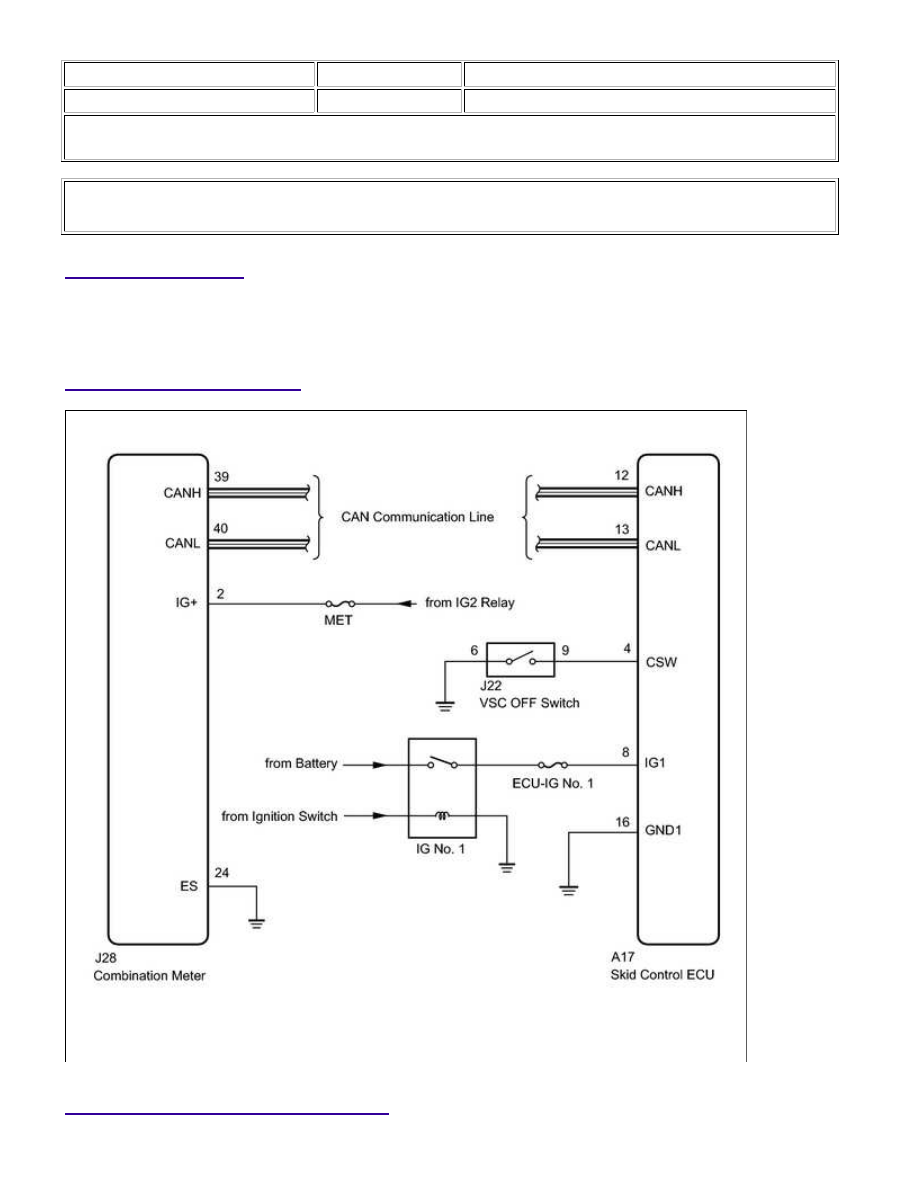
WIRING DIAGRAM

INSPECTION PROCEDURE

BRAKE CONTROL: VEHICLE STABILITY CONTROL SYSTEM: Sli...

A

NOTICE:

When replacing the VSC actuator assembly, perform zero point calibration 


.

PROCEDURE

1.

INSPECT CAN COMMUNICATION SYSTEM

(a) Check if a CAN communication system DTC is output 


.

Result

RESULT

PROCEED TO

DTC is not output

A

DTC is output

B

B

GO TO CAN COMMUNICATION SYSTEM

2.

PERFORM ACTIVE TEST USING TECHSTREAM (SLIP INDICATOR LIGHT)

(a) Connect the Techstream to the DLC3.

(b) Turn the ignition switch to ON.

(c) Turn the Techstream on.

(d) Select the Active Test mode and operate the SLIP indicator light using the Techstream.

ABS/VSC/TRAC

TESTER DISPLAY

TEST PART

CONTROL RANGE

DIAGNOSTIC NOTE

Slip Indicator Light

SLIP indicator light

ON / OFF

Observe combination meter

(e) Check that the SLIP indicator light turns on and off in the combination meter when using the

Techstream.

OK:

The SLIP indicator light turns on and off in accordance with the Techstream operation.

HINT:

NG

GO TO METER / GAUGE SYSTEM

BRAKE CONTROL: VEHICLE STABILITY CONTROL SYSTEM: Sli...

OK

OK

3.

INSPECT VSC OFF SWITCH

(a) Remove the VSC OFF switch 


.

(b) Measure the resistance according to the value(s) in the table below.

Standard Resistance:

TESTER CONNECTION

SWITCH CONDITION

SPECIFIED CONDITION

6 - 9

Switch is pressed

Below 1 Ω

Switch is not pressed

10 kΩ or higher

NG

REPLACE VSC OFF SWITCH

4.

CHECK HARNESS AND CONNECTOR (SKID CONTROL ECU - VSC OFF SWITCH)

(a) Disconnect the A17 ECU connector.

BRAKE CONTROL: VEHICLE STABILITY CONTROL SYSTEM: Sli...

(b) Disconnect the J22 VSC OFF switch connector.

(c) Measure the resistance according to the value(s) in the table below.

Standard Resistance:

TESTER CONNECTION

CONDITION

SPECIFIED CONDITION

A17-4 (CSW) - J22-9

Always

Below 1 Ω

A17-4 (CSW) - Body ground

Always

10 kΩ or higher

NG

REPAIR OR REPLACE HARNESS OR CONNECTOR

OK

REPLACE VSC ACTUATOR ASSEMBLY

BRAKE CONTROL: VEHICLE STABILITY CONTROL SYSTEM: Sli...


Content   ..  265  266  267  268   ..