Toyota Tundra (2015 year). Manual - part 2303


  Index      Toyota     Toyota Tundra (2015 year) - Service and Repair Manual


Search            copyright infringement  


Content   ..  2301  2302  2303  2304   ..


Toyota Tundra (2015 year). Manual - part 2303


Last Modified: 9-16-2014

6.6 A

Doc ID: RM000002VY101FX

Model Year: 2015

Model: Tundra

Prod Date Range: [08/2014 -           ]

Title: AIR CONDITIONING: FRONT EVAPORATOR TEMPERATURE SENSOR: REMOVAL; 2015 MY Tundra [08/2014 -

       ]

REMOVAL

1. REMOVE AIR CONDITIONING UNIT


.

2. REMOVE NO. 3 AIR DUCT SUB-ASSEMBLY 

3. REMOVE AIR CONDITIONING AMPLIFIER ASSEMBLY 

4. REMOVE BLOWER ASSEMBLY

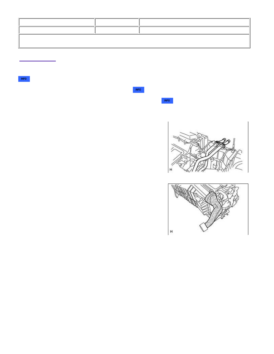
(a) Detach the 3 claws and remove the heater clamp.

(b) Remove the No. 1 cooling unit packing and No. 2 cooling unit

packing.

AIR CONDITIONING: FRONT EVAPORATOR TEMPERATURE SEN...

(c) Remove the 6 screws and detach the 3 claws, and remove the

blower assembly.

5. REMOVE NO. 1 COOLER EVAPORATOR SUB-ASSEMBLY

(a) Remove the No. 1 cooler evaporator sub-assembly from the

blower assembly.

6. REMOVE NO. 1 COOLER THERMISTOR

(a) Remove the No. 1 cooler thermistor from the No. 1 cooler

evaporator sub-assembly.

AIR CONDITIONING: FRONT EVAPORATOR TEMPERATURE SEN...

Last Modified: 9-16-2014

6.6 G

Doc ID: RM000001HA602YX

Model Year: 2015

Model: Tundra

Prod Date Range: [08/2014 -           ]

Title: AIR CONDITIONING: FRONT EVAPORATOR TEMPERATURE SENSOR: INSPECTION; 2015 MY Tundra

[08/2014 -        ]

INSPECTION

1. INSPECT NO. 1 COOLER THERMISTOR

(a) Measure the resistance according to the value(s) in the table

below.

Standard Resistance:

TESTER CONNECTION

CONDITION

SPECIFIED CONDITION

1 - 2

-10°C (14°F)

7.30 to 9.10 kΩ

-5°C (23°F)

5.65 to 6.95 kΩ

0°C (32°F)

4.40 to 5.35 kΩ

5°C (41°F)

3.40 to 4.15 kΩ

10°C (50°F)

2.70 to 3.25 kΩ

15°C (59°F)

2.14 to 2.58 kΩ

20°C (68°F)

1.71 to 2.05 kΩ

25°C (77°F)

1.38 to 1.64 kΩ

30°C (86°F)

1.11 to 1.32 kΩ

NOTICE:

HINT:

As the temperature increases, the resistance decreases (see the

graph).

Text in Illustration

*1

Sensor

*a

Component without harness connected

(No. 1 Cooler Thermistor)

*b

Resistance (kΩ)

*c

Temperature (°C (°F))

If the result is not as specified, replace the sensor.

AIR CONDITIONING: FRONT EVAPORATOR TEMPERATURE SEN...

Last Modified: 9-16-2014

6.6 A

Doc ID: RM000002VY201EX

Model Year: 2015

Model: Tundra

Prod Date Range: [08/2014 -           ]

Title: AIR CONDITIONING: FRONT EVAPORATOR TEMPERATURE SENSOR: INSTALLATION; 2015 MY Tundra

[08/2014 -        ]

INSTALLATION

1. INSTALL NO. 1 COOLER THERMISTOR

NOTICE:

If reusing the evaporator, do not insert the No. 1 cooler thermistor into a location where the No. 1 cooler

thermistor was previously inserted. Insert the No. 1 cooler thermistor within range C shown in the
illustration.

(a) Install the No. 1 cooler thermistor to the No. 1 cooler evaporator sub-assembly as shown in the illustration.

AREA

STANDARD DIMENSION

a

48 mm (1.89 in.)

b

8.7 to 9.0 mm (0.343 to 0.354 in.)

c

34.3 mm (1.35 in.)

d

47.7 mm (1.88 in.)

e

48 to 52 mm (1.89 to 2.04 in.)

2. INSTALL NO. 1 COOLER EVAPORATOR SUB-ASSEMBLY

(a) Install the No. 1 cooler evaporator sub-assembly to the blower assembly.

3. INSTALL BLOWER ASSEMBLY

(a) Attach the 3 claws to install the blower assembly.

(b) Install the 6 screws.

AIR CONDITIONING: FRONT EVAPORATOR TEMPERATURE SEN...


Content   ..  2301  2302  2303  2304   ..