Toyota Tundra (2015 year). Manual - part 2068


  Index      Toyota     Toyota Tundra (2015 year) - Service and Repair Manual


Search            copyright infringement  


Content   ..  2066  2067  2068  2069   ..


Toyota Tundra (2015 year). Manual - part 2068


Last Modified: 9-16-2014

6.6 A

Doc ID: RM000002S5J03BX

Model Year: 2015

Model: Tundra

Prod Date Range: [08/2014 -           ]

Title: 3UR-FE ENGINE MECHANICAL: CYLINDER BLOCK: DISASSEMBLY; 2015 MY Tundra [08/2014 -        ]

DISASSEMBLY

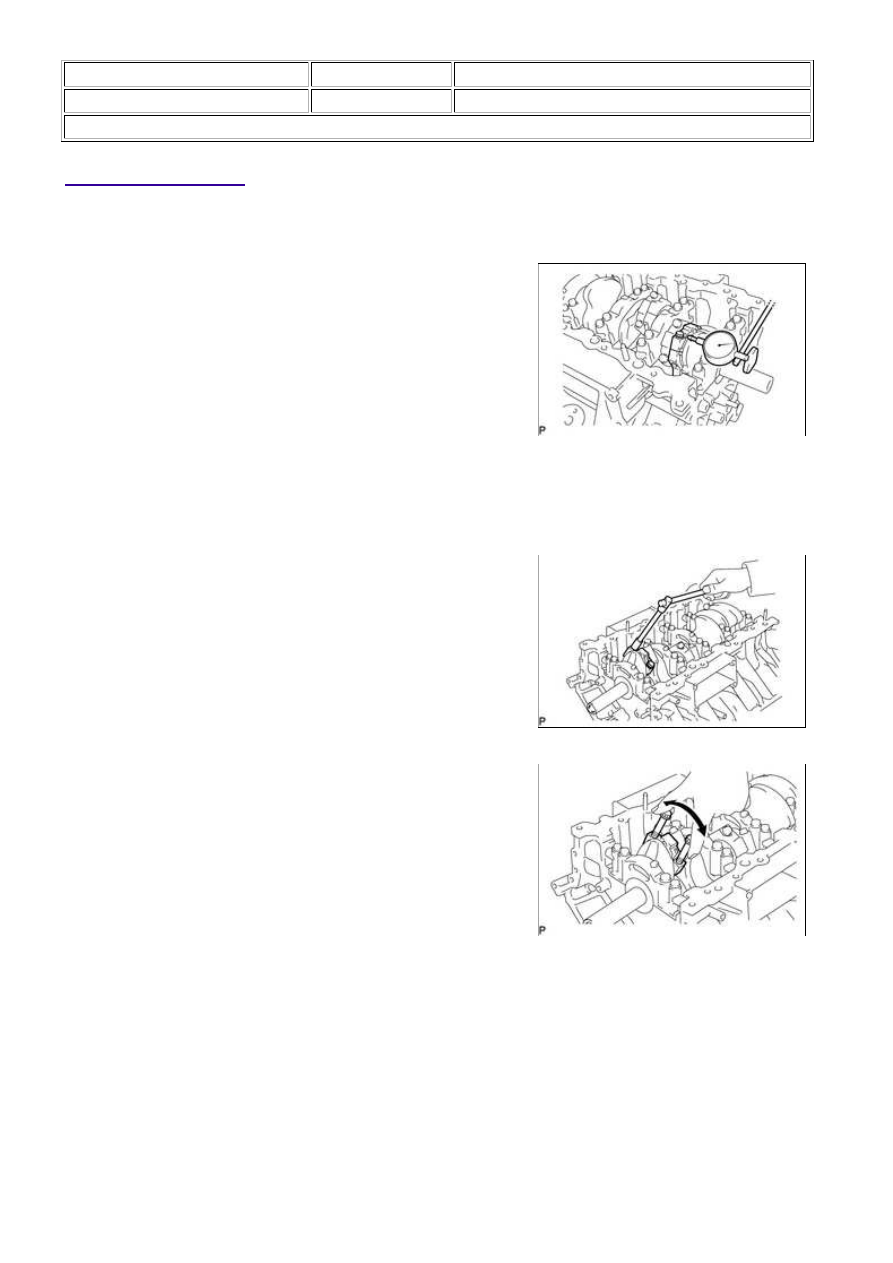
1. INSPECT CONNECTING ROD THRUST CLEARANCE

(a) Using a dial indicator, measure the thrust clearance while

moving the connecting rod back and forth.

Standard thrust clearance:

0.15 to 0.55 mm (0.00591 to 0.0217 in.)

Maximum thrust clearance:

0.70 mm (0.0276 in.)

If the thrust clearance is greater than the maximum, replace

one or more connecting rods as necessary.

If necessary, replace the crankshaft.

2. INSPECT CONNECTING ROD OIL CLEARANCE

(a) Check that the front mark on the connecting rod and cap are aligned to ensure correct reassembly.

(b) Remove the 2 connecting rod cap bolts.

(c) Using the 2 removed connecting rod cap bolts, remove the

connecting rod cap and lower bearing by wiggling the

connecting rod cap right and left.

HINT:

Keep the lower bearing inserted to the connecting rod cap.

(d) Clean the crank pin and bearing.

(e) Check the crank pin and bearing for pitting and scratches.

If the crank pin or bearing is damaged, replace the bearings. If necessary, replace the crankshaft.

3UR-FE ENGINE MECHANICAL: CYLINDER BLOCK: DISASSE...

forward.

Torque:

40 N·m {408 kgf·cm, 30ft·lbf}

NOTICE:

Do not turn the crankshaft.

(j) Tighten the cap bolts another 90° as shown in the illustration.

(k) Check that the painted marks are now at a 90° angle to the front.

NOTICE:

Do not turn the crankshaft.

(l) Remove the 2 connecting rod cap bolts.

3UR-FE ENGINE MECHANICAL: CYLINDER BLOCK: DISASSE...

(m) Using the 2 removed connecting rod cap bolts, remove the

connecting rod cap and lower bearing by wiggling the

connecting rod cap right and left.

HINT:

Keep the lower bearing inserted to the connecting rod cap.

(n) Measure the Plastigage at its widest point.

Standard oil clearance:

0.025 to 0.050 mm (0.000984 to 0.00197 in.)

Maximum oil clearance:

0.070 mm (0.00276 in.)

If the oil clearance is greater than the maximum, replace the

bearings. If necessary, replace the crankshaft.

HINT:

If replacing a bearing, replace it with one that has the same
number as its respective connecting rod cap. Each bearing's
standard thickness is indicated by a 1, 2, 3 or 4 mark on its
surface.
Select the correct bearing by adding together the number
marks imprinted on the connecting rod big end and crank pin.

HINT:

Example:

Connecting rod "1" + Crank pin "2" = 3 (Use bearing "3")

Reference:

Standard sized bearing center wall thickness:

MARK

THICKNESS

2

1.489 to 1.492 mm (0.0586 to 0.0587 in.)

3

1.492 to 1.495 mm (0.0587 to 0.0589 in.)

4

1.495 to 1.498 mm (0.0589 to 0.0590 in.)

5

1.498 to 1.501 mm (0.0590 to 0.0591 in.)

6

1.501 to 1.504 mm (0.0591 to 0.0592 in.)

7

1.504 to 1.507 mm (0.0592 to 0.0593 in.)

Connecting rod big end inside diameter:

MARK

THICKNESS

1

59.000 to 59.006 mm (2.32283 to 2.32306 in.)

2

59.007 to 59.012 mm (2.32311 to 2.32330 in.)

3

59.013 to 59.018 mm (2.32334 to 2.32354 in.)

4

59.019 to 59.024 mm (2.32358 to 2.32377 in.)

Crankshaft pin diameter:

3UR-FE ENGINE MECHANICAL: CYLINDER BLOCK: DISASSE...

MARK

THICKNESS

1

55.995 to 56.000 mm (2.20452 to 2.20472 in.)

2

55.989 to 55.994 mm (2.20429 to 2.20448 in.)

3

55.982 to 55.998 mm (2.20401 to 2.20464 in.)

(o) Completely remove the Plastigage.

(p) Perform the inspection above for each cylinder.

3. REMOVE PISTON AND CONNECTING ROD

(a) Using a ridge reamer, remove all the carbon from the top of

the cylinder.

(b) Remove the 16 cap bolts, 8 connecting rod caps and 8 lower bearings.

Arrange the piston and connecting rod in the correct order.

4. REMOVE CONNECTING ROD BEARING

(a) Remove the connecting rod bearings from the connecting rods and connecting rod caps.

HINT:

Arrange the removed parts in the correct order.

5. REMOVE PISTON RING SET

HINT:

Arrange the piston rings in the correct order.

(a) Using a piston ring expander, remove the 2 compression

rings.

(b) Remove the 2 side rails and oil ring expander by hand.

6. REMOVE PISTON WITH PIN SUB-ASSEMBLY

(a) Disconnect the connecting rod from the piston.

3UR-FE ENGINE MECHANICAL: CYLINDER BLOCK: DISASSE...


Content   ..  2066  2067  2068  2069   ..