Toyota Tundra (2015 year). Manual - part 2013


  Index      Toyota     Toyota Tundra (2015 year) - Service and Repair Manual


Search            copyright infringement  


Content   ..  2011  2012  2013  2014   ..


Toyota Tundra (2015 year). Manual - part 2013


INSPECTION PROCEDURE

HINT:

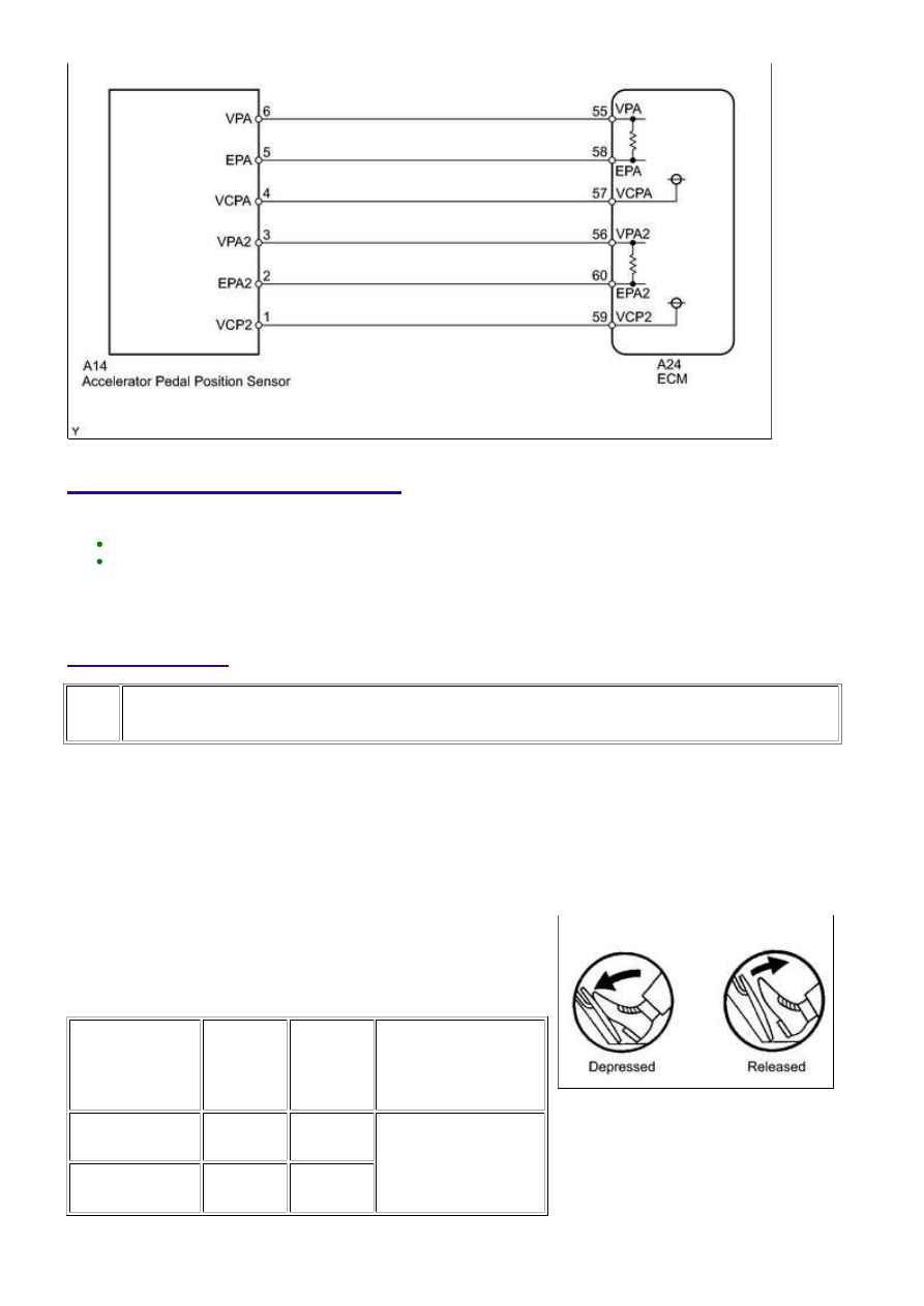
These DTCs relate to the Accelerator Pedal Position (APP) sensor.
Read freeze frame data using the Techstream. Freeze frame data records the engine condition when
malfunctions are detected. When troubleshooting, freeze frame data can help determine if the vehicle
was moving or stationary, if the engine was warmed up or not, if the air-fuel ratio was lean or rich, and
other data from the time the malfunction occurred.

PROCEDURE

1.

READ VALUE USING TECHSTREAM (ACCELERATOR PEDAL POSITION SENSOR)

(a) Connect the Techstream to the DLC3.

(b) Turn the ignition switch to ON and turn the Techstream

on.

(c) Enter the following menus: Powertrain / Engine and ECT

/ Data List / ETCS / Accel Sensor Out No. 1 and Accel
Sensor Out No. 2.

(d) Read the value displayed on the Techstream.

Standard voltage:

ACCELERATOR

PEDAL

OPERATION

ACCEL

SENSOR

OUT NO. 1

ACCEL

SENSOR

OUT NO. 2

DIFFERENCE BETWEEN

ACCEL SENSOR OUT

NO. 1 AND ACCEL

SENSOR OUT NO. 2

Released

0.5 to 1.1

V

1.2 to 2.0

V

More than 0.02 V

Depressed

2.6 to 4.5

V

3.4 to 4.75

V

3UR-FE ENGINE CONTROL SYSTEM: SFI SYSTEM: P2120,P2122...

A

OK

Result

RESULT

PROCEED TO

NG

A

OK

B

B

GO TO STEP 5

2.

CHECK HARNESS AND CONNECTOR (ACCELERATOR PEDAL POSITION SENSOR -
ECM)

(a) Disconnect the A14 APP sensor connector.

(b) Disconnect the A24 ECM connector.

(c) Measure the resistance according to the value(s) in the table below.

Standard resistance:

TESTER CONNECTION

CONDITION

SPECIFIED CONDITION

A14-6 (VPA) - A24-55 (VPA)

Always

Below 1 Ω

A14-5 (EPA) - A24-58 (EPA)

Always

Below 1 Ω

A14-4 (VCPA) - A24-57 (VCPA)

Always

Below 1 Ω

A14-3 (VPA2) - A24-56 (VPA2)

Always

Below 1 Ω

A14-2 (EPA2) - A24-60 (EPA2)

Always

Below 1 Ω

A14-1 (VCP2) - A24-59 (VCP2)

Always

Below 1 Ω

A14-6 (VPA) or A24-55 (VPA) - Body ground

Always

10 kΩ or higher

A14-5 (EPA) or A24-58 (EPA) - Body ground

Always

10 kΩ or higher

A14-4 (VCPA) or A24-57 (VCPA) - Body ground

Always

10 kΩ or higher

A14-3 (VPA2) or A24-56 (VPA2) - Body ground

Always

10 kΩ or higher

A14-2 (EPA2) or A24-60 (EPA2) - Body ground

Always

10 kΩ or higher

A14-1 (VCP2) or A24-59 (VCP2) - Body ground

Always

10 kΩ or higher

NG

REPAIR OR REPLACE HARNESS OR CONNECTOR

3UR-FE ENGINE CONTROL SYSTEM: SFI SYSTEM: P2120,P2122...

OK

NEXT

3.

CHECK ECM (VCPA AND VCP2 VOLTAGE)

(a) Disconnect the A14 APP sensor connector.

(b) Turn the ignition switch to ON.

(c) Measure the voltage according to the value(s) in the

table below.

Standard voltage:

TESTER CONNECTION

SWITCH

CONDITION

SPECIFIED

CONDITION

A14-4 (VCPA) - A14-5

(EPA)

Ignition switch ON 4.5 to 5.5 V

A14-1 (VCP2) - A14-2

(EPA2)

Ignition switch ON 4.5 to 5.5 V

NG

REPLACE ECM

4.

REPLACE ACCELERATOR PEDAL ASSEMBLY

(a) Replace the accelerator pedal assembly 


.

5.

CHECK WHETHER DTC OUTPUT RECURS (ACCELERATOR PEDAL POSITION
SENSOR DTCS)

(a) Connect the Techstream to the DLC3.

(b) Turn the ignition switch to ON and turn the Techstream on.

(c) Clear DTCs 


.

(d) Start the engine.

(e) Allow the engine to idle for 15 seconds.

(f) Enter the following menus: Powertrain / Engine and ECT / Trouble Codes.

(g) Read DTCs.

3UR-FE ENGINE CONTROL SYSTEM: SFI SYSTEM: P2120,P2122...

Result

RESULT

PROCEED TO

P2120, P2122, P2123, P2125, P2127, P2128, and/or P2138 are output

A

No DTC is output

B

B

SYSTEM OK

A

REPLACE ECM

3UR-FE ENGINE CONTROL SYSTEM: SFI SYSTEM: P2120,P2122...


Content   ..  2011  2012  2013  2014   ..