Toyota Tundra (2015 year). Manual - part 1999


  Index      Toyota     Toyota Tundra (2015 year) - Service and Repair Manual


Search            copyright infringement  


Content   ..  1997  1998  1999  2000   ..


Toyota Tundra (2015 year). Manual - part 1999


OK

RESULT

PROCEED TO

HINT:

GO TO STEP 102

A

REPAIR OR REPLACE FUEL LINE

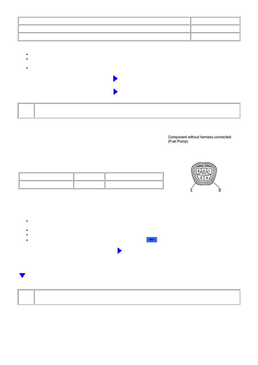
102. INSPECT FUEL PUMP

(a) Remove the fuel suction tube.

(b) Measure the resistance according to the value(s) in the table

below.

Standard resistance:

TESTER CONNECTION

CONDITION

SPECIFIED CONDITION

4 (B) - 5 (E)

20°C

0.2 to 3.0 Ω

HINT:

Make sure there is no foreign matter such as iron particles on the fuel pump and no signs that the fuel pump was
stuck.
Make sure the internal connector is securely connected.
Make sure the fuel pump filter is not clogged.

Perform "Inspection After Repair" after replacing the fuel pump 


.

NG

REPLACE FUEL PUMP

103. CHECK PURGE VSV

3UR-FE ENGINE CONTROL SYSTEM: SFI SYSTEM: P1604; Startabi...

OK

(b) Start the engine.

(c) Idle the engine.

Standard:

Air does not flow

HINT:

When this inspection is performed, the MIL may illuminate. After finishing the inspection, check and clear DTCs


.

NG

INSPECT PURGE VSV

104. CHECK FUEL INJECTOR

RESULT

PROCEED TO

4000 ppm or higher

A

Less than 4000 ppm

B

HINT:

If the concentration is 4000 ppm or higher, a fuel injector may have a sealing problem.

Perform "Inspection After Repair" after replacing the fuel injector assembly 


.

B

GO TO STEP 105

A

REPLACE FUEL INJECTOR

105. CHECK INTAKE VALVE

3UR-FE ENGINE CONTROL SYSTEM: SFI SYSTEM: P1604; Startabi...

A

(a) Check if carbon is on the intake valves.

RESULT

PROCEED TO

Carbon present

A

No carbon present

B

B

GO TO STEP 106

A

CLEAN INTAKE VALVE

106. READ VALUE USING TECHSTREAM (ISC LEARNING VALUE)

(a) Connect the Techstream to the DLC3.

(b) Turn the ignition switch to ON.

(c) Start the engine, turn off all accessory switches and warm up the engine until the engine coolant

temperature stabilizes.

(d) Using the Techstream, select and read [ISC Learning Value] in the Data List.

DATA LIST ITEM

RESULT

SUSPECTED AREA

PROCEED TO

ISC Learning Value

(engine displacement (liters) x 0.9) or more

Valve timing

Compression

A

Less than (engine displacement (liters) x 0.9)

-

B

B

GO TO STEP 108

107. CHECK CYLINDER COMPRESSION PRESSURE

(a) Inspect the compression 


.

HINT:

Perform "Inspection After Repair" after replacing the engine assembly 


.

NG

REPAIR OR REPLACE ENGINE ASSEMBLY

OK

ADJUST VALVE TIMING

108. INSPECT ENGINE COOLANT TEMPERATURE SENSOR

(a) Inspect the engine coolant temperature sensor 


.

HINT:

3UR-FE ENGINE CONTROL SYSTEM: SFI SYSTEM: P1604; Startabi...

OK

OK

OK

Perform "Inspection After Repair" after replacing the engine coolant temperature sensor 


.

NG

REPLACE ENGINE COOLANT TEMPERATURE SENSOR

109. CHECK CRANKSHAFT POSITION SENSOR

OK:

Sensor is installed correctly.

NG

SECURELY REINSTALL SENSOR

110. CHECK CAMSHAFT POSITION SENSOR

OK:

Sensor is installed correctly.

NG

SECURELY REINSTALL SENSOR

111. CHECK HARNESS AND CONNECTOR (CRANKSHAFT POSITION SENSOR - ECM)

(a) Disconnect the crankshaft position sensor connector.

(b) Disconnect the ECM connector.

(c) Measure the resistance according to the value(s) in the table below.

Standard resistance:

TESTER CONNECTION

CONDITION

SPECIFIED CONDITION

D3-1 (NE+) - D74-110 (NE+)

Always

Below 1 Ω

D3-2 (NE-) - D74-111 (NE-)

Always

Below 1 Ω

D3-3 (VC) - D74-66 (VCV2)

Always

Below 1 Ω

3UR-FE ENGINE CONTROL SYSTEM: SFI SYSTEM: P1604; Startabi...


Content   ..  1997  1998  1999  2000   ..