Toyota Tundra (2015 year). Manual - part 1997


  Index      Toyota     Toyota Tundra (2015 year) - Service and Repair Manual


Search            copyright infringement  


Content   ..  1995  1996  1997  1998   ..


Toyota Tundra (2015 year). Manual - part 1997


OK

OK

HINT:

REPAIR OR REPLACE HARNESS OR CONNECTOR

81.

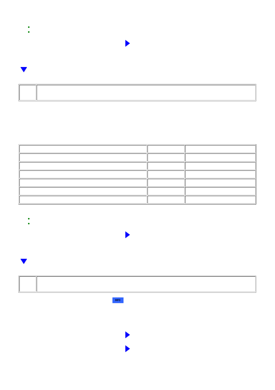
CHECK HARNESS AND CONNECTOR (CAMSHAFT POSITION SENSOR - ECM)

(a) Disconnect the camshaft position sensor connector.

(b) Disconnect the ECM connector.

(c) Measure the resistance according to the value(s) in the table below.

Standard resistance:

TESTER CONNECTION

CONDITION

SPECIFIED CONDITION

D6-1 (G2) - D74-90 (G2)

Always

Below 1 Ω

D6-2 (G-) - D74-89 (G2-)

Always

Below 1 Ω

D6-3 (VC) - D74-66 (VCV2)

Always

Below 1 Ω

D6-1 (G2) or D74-90 (G2) - Body ground

Always

10 kΩ or higher

D6-2 (G-) or D74-89 (G2-) - Body ground

Always

10 kΩ or higher

D6-3 (VC) or D74-66 (VCV2) - Body ground

Always

10 kΩ or higher

HINT:

REPAIR OR REPLACE HARNESS OR CONNECTOR

82.

CHECK CRANKSHAFT POSITION SENSOR

(a) Replace the crankshaft position sensor 


.

(b) Check the engine start operation.

OK:

Malfunction has been repaired successfully.

NG

GO TO STEP 83

OK

END (CRANKSHAFT POSITION SENSOR IS DEFECTIVE)

3UR-FE ENGINE CONTROL SYSTEM: SFI SYSTEM: P1604; Startabi...

A

83.

CHECK CAMSHAFT POSITION SENSOR

(a) Replace the camshaft position sensor 


.

(b) Check the engine start operation.

OK:

Malfunction has been repaired successfully.

NG

REPLACE ECM

OK

END (CAMSHAFT POSITION SENSOR IS DEFECTIVE)

84.

READ VALUE USING TECHSTREAM (ISC LEARNING VALUE)

(a) Connect the Techstream to the DLC3.

(b) Turn the ignition switch to ON.

(c) Start the engine and warm it up until the engine coolant temperature stabilizes with the A/C switch and

all the accessory switches should be off

(d) Using the Techstream, select and read [ISC Learning Value] in the Data List.

DATA LIST ITEM

RESULT

SUSPECTED AREA

PROCEED TO

ISC Learning Value

(engine displacement (liters) x 0.9) or more

Valve timing

Compression

A

Less than (engine displacement (liters) x 0.9)

-

B

B

GO TO STEP 86

85.

CHECK CYLINDER COMPRESSION PRESSURE

(a) Inspect the compression 


.

HINT:

Perform "Inspection After Repair" after repairing or replacing the engine assembly 


.

NG

REPAIR OR REPLACE ENGINE ASSEMBLY

OK

CHECK VALVE TIMING

86.

INSPECT ENGINE COOLANT TEMPERATURE SENSOR

(a) Inspect the engine coolant temperature sensor 


.

3UR-FE ENGINE CONTROL SYSTEM: SFI SYSTEM: P1604; Startabi...

OK

OK

A

HINT:

Perform "Inspection After Repair" after replacing the engine coolant temperature sensor 


.

NG

REPLACE ENGINE COOLANT TEMPERATURE SENSOR

87.

CHECK FUEL PRESSURE

HINT:

For the fuel pressure inspection, refer to the following procedures 


.

(a) Attach a fuel pressure gauge and check the fuel pressure when cranking the engine and after stopping

the engine.

VEHICLE STATE

SPECIFIED CONDITION

Cranking engine

304 to 343 kPa (3.1 to 3.5 kgf/cm 

2

 )

5 minutes after stopping engine

147 kPa (1.5 kgf/cm 

2

 ) or more

NG

GO TO STEP 93

88.

READ VALUE USING TECHSTREAM (LONG FT)

(a) Connect the Techstream to the DLC3.

(b) Turn the ignition switch to ON.

(c) Using the Techstream, select and read [Long FT] in the Data List.

DATA LIST ITEM

RESULT

SUSPECTED AREA

PROCEED TO

Long FT

-15 to +15%

Wire harness or connector

Fuel

A

+15% or more, or less than -15%

Fuel injector

B

HINT:

Perform "Inspection After Repair" after replacing the fuel injector assembly 


.

B

REPLACE FUEL INJECTOR

3UR-FE ENGINE CONTROL SYSTEM: SFI SYSTEM: P1604; Startabi...

A

OK

89.

PERFORM SIMULATION TEST

(a) Check if the idling speed after starting the engine is currently stable and has always been stable in the

past.

PROBLEM SYMPTOM

SUSPECTED AREA

PROCEED TO

A

All current and past idling speeds are stable

Fuel

B

HINT:

Through the customer problem analysis, confirm the fuel being used and the location at which the fuel was added

to check if the malfunction is caused by the fuel in the vehicle.

B

REPLACE FUEL

90.

CHECK CRANKSHAFT POSITION SENSOR

OK:

Sensor is installed correctly.

NG

SECURELY REINSTALL SENSOR

91.

CHECK HARNESS AND CONNECTOR (CRANKSHAFT POSITION SENSOR - ECM)

(a) Disconnect the crankshaft position sensor connector.

(b) Disconnect the ECM connector.

(c) Measure the resistance according to the value(s) in the table below.

Standard resistance:

TESTER CONNECTION

CONDITION

SPECIFIED CONDITION

D3-1 (NE+) - D74-110 (NE+)

Always

Below 1 Ω

D3-2 (NE-) - D74-111 (NE-)

Always

Below 1 Ω

D3-3 (VC) - D74-66 (VCV2)

Always

Below 1 Ω

D3-1 (NE+) or D74-110 (NE+) - Body ground

Always

10 kΩ or higher

D3-2 (NE-) or D74-111 (NE-) - Body ground

Always

10 kΩ or higher

3UR-FE ENGINE CONTROL SYSTEM: SFI SYSTEM: P1604; Startabi...


Content   ..  1995  1996  1997  1998   ..