Content .. 1986 1987 1988 1989 ..
Toyota Tundra (2015 year). Manual - part 1988
OK
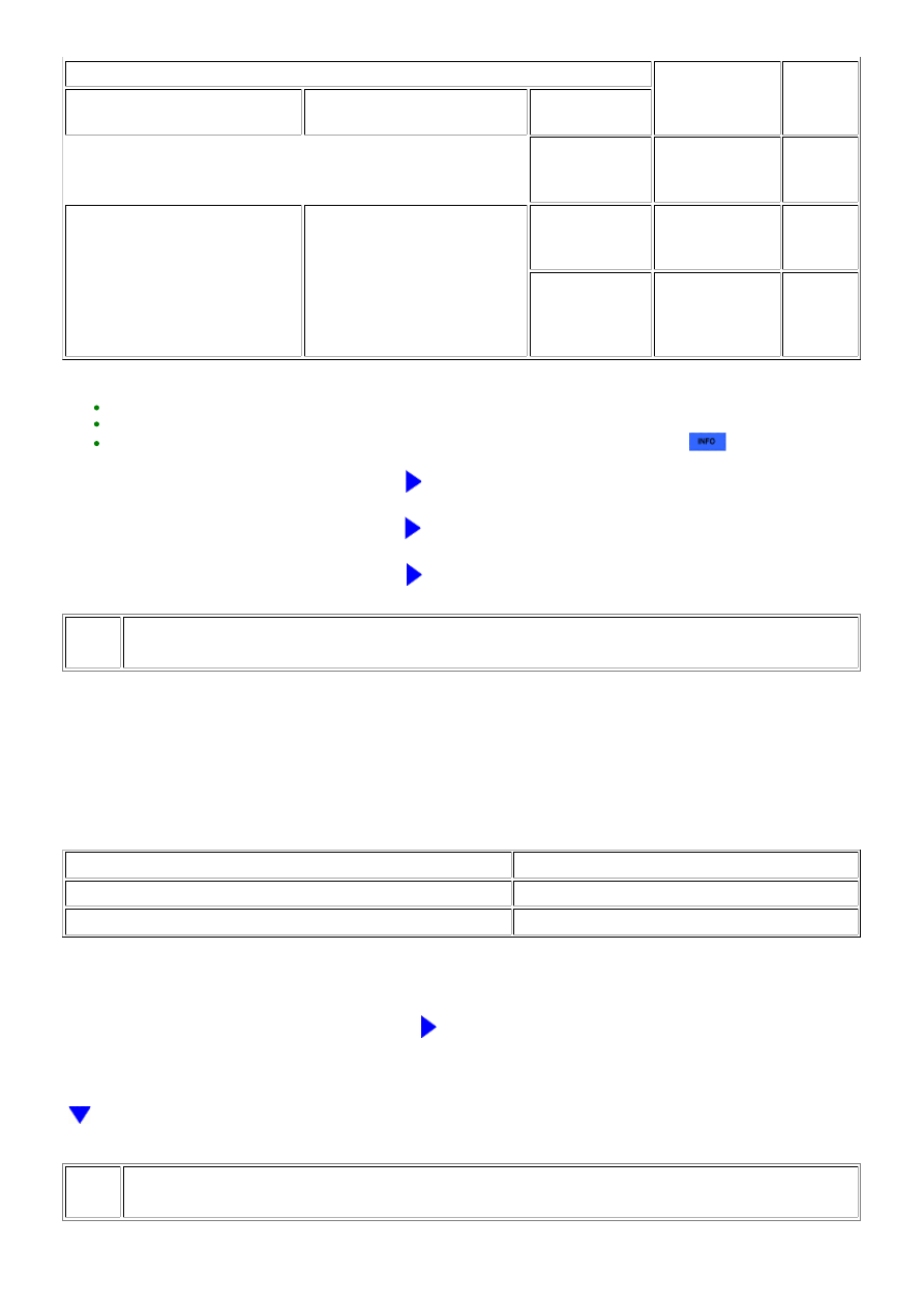
FREEZE FRAME DATA ITEM
SUSPECTED AREA
PROCEED
TO
COOLANT TEMP, AMBIENT
TEMPERATURE, INTAKE AIR
COOLANT TEMP, AMBIENT
TEMPERATURE
FUEL PUMP DUTY
frame data is 0%
Fuel pump control
system
C
Difference between Coolant Temp,
Ambient Temperature and Intake
Air is less than 10°C*2
-
frame data is 0%
Fuel pump control
system
C
All 5 sets of
freeze frame
data are except
0%
-
B
HINT:
*1: A long time had not elapsed after stopping the engine.
*2: A long time had elapsed after stopping the engine.
Perform "Inspection After Repair" after replacing the engine coolant temperature sensor
.
B
GO TO STEP 11
C
CHECK FUEL PUMP CONTROL SYSTEM
A
REPLACE ENGINE COOLANT TEMPERATURE SENSOR
11.
PERFORM ACTIVE TEST USING TECHSTREAM (CONTROL THE FUEL PUMP / SPEED)
(a) Connect the Techstream to the DLC3.
(b) Turn the ignition switch to ON.
(c) Using the Techstream, select the [Control the Fuel Pump / Speed] Active Test.
(d) When performing the Active Test, check for an operating sound from the fuel pump.
Standard:
CONTROL THE FUEL PUMP / SPEED
SPECIFIED CONDITION
ON
Operating sound heard
OFF
Operating sound not heard
HINT:
REPAIR FUEL PUMP CONTROL SYSTEM
12.
CHECK HARNESS AND CONNECTOR (FUEL INJECTOR POWER SOURCE)
3UR-FE ENGINE CONTROL SYSTEM: SFI SYSTEM: P1604; Startabi...