Toyota Tundra (2015 year). Manual - part 1986


  Index      Toyota     Toyota Tundra (2015 year) - Service and Repair Manual


Search            copyright infringement  


Content   ..  1984  1985  1986  1987   ..


Toyota Tundra (2015 year). Manual - part 1986


malfunction.

When 2 to 3 minutes have elapsed after stopping the engine: Fuel pressure loss due to the

pressure regulator failing to maintain the fuel pressure.

When 15 to 120 minutes have elapsed after stopping the engine: Problem with injector fuel

seal.

When a long time has elapsed after stopping the engine: Pressure regulator is stuck open.

(2) Systems to inspect.

Intake system

1. 

Ignition system

2. 

Fuel system

3. 

2. INSPECTION FLOW

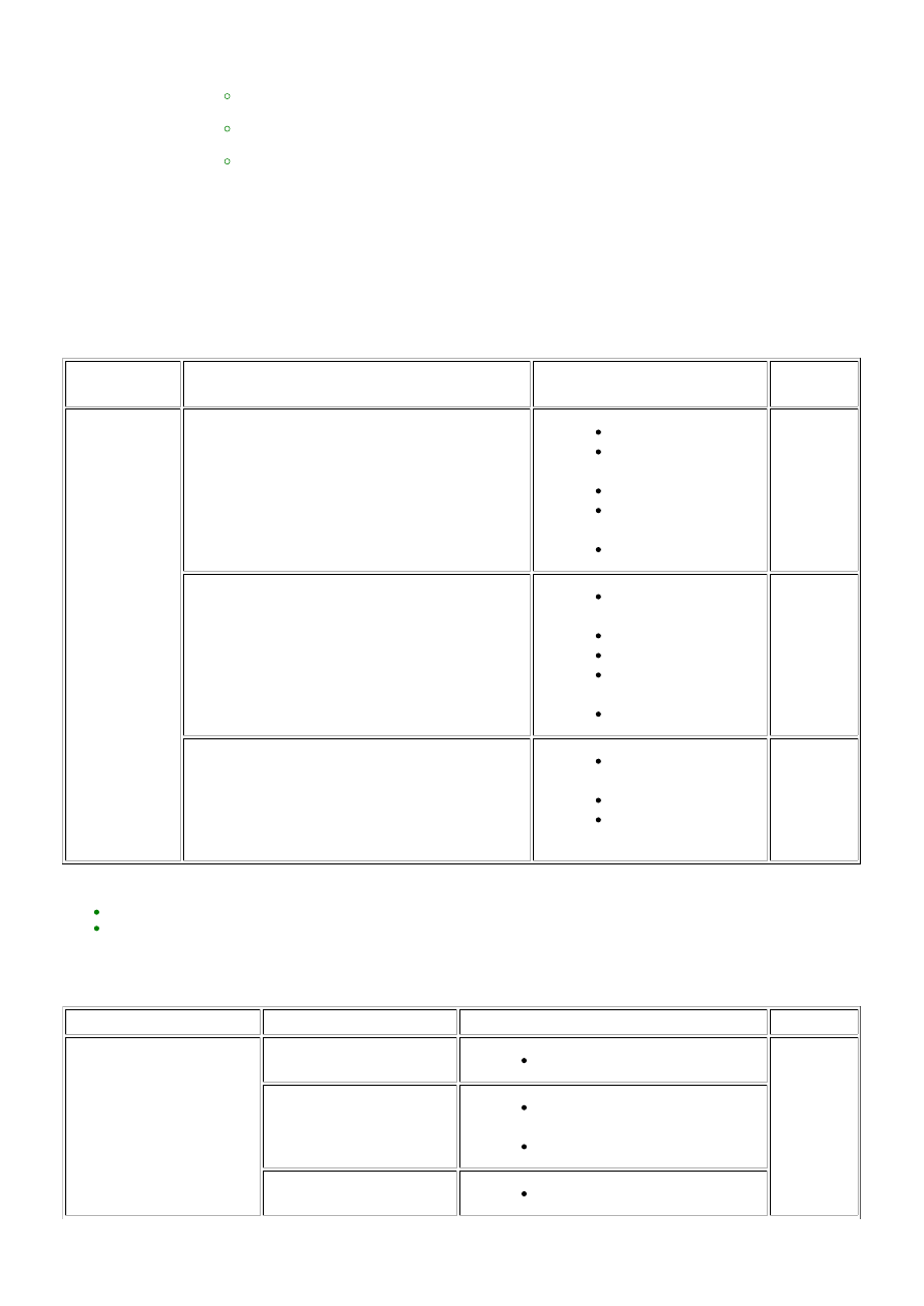
(a) Freeze frame data exists, but the malfunction (starting difficulty) has not reoccurred and the malfunction

conditions are unknown.

FREEZE FRAME

DATA ITEM

RESULT

SUSPECTED AREA

PROCEDURE

Engine Speed

0 rpm (no engine cranking at all)

Battery fully depleted

Engine assembly

(excess friction)

Starter

Crankshaft position

sensor

ECM

4 to 9

100 to 250 rpm (engine cranks but no initial

combustion*1)

Fuel pump control

system

Ignition system

Immobiliser system

Engine coolant

temperature sensor

Fuel injection system

10 to 14

250 rpm or higher (combustion occurs but initial

combustion and starter turnoff*2 occur late)

Engine assembly

(compression loss)

Fuel injection system

Fuel pump control

system

15 to 23

HINT:

*1: First combustion after cranking begins.
*2: Condition when engine speed increases and starter can be turned off.

(b) When the malfunction (starting difficulty) can be reproduced, or when malfunction conditions are known.

(1) Problem symptoms

PROBLEM SYMPTOM

SUSPECTED AREA

SUSPECTED COMPONENT

PROCEDURE

The engine does not crank

Battery malfunction

Battery fully depleted

26 to 31

Starting system

Starter (includes pinion gear wear

or tooth damage)

Starting system

Immobiliser system

Immobiliser system

3UR-FE ENGINE CONTROL SYSTEM: SFI SYSTEM: P1604; Startabi...

PROBLEM SYMPTOM

SUSPECTED AREA

SUSPECTED COMPONENT

PROCEDURE

Engine assembly

Engine assembly (excess friction)

Drive plate wear or tooth damage

Cranking speed too low

Battery malfunction

Battery fully depleted

32 to 34

Starting system

Starter

Engine assembly

Engine assembly (excess friction)

Cranking speed too high

Engine assembly

Engine assembly (compression

loss)

There is no initial

combustion

Fuel supply problem

Cannot maintain pressure due to

pressure regulator malfunction

Fuel injector leak

Fuel leak from fuel line

Fuel pump control system

Fuel pump

35 to 50

Ignition system malfunction

Spark plug

Crankshaft position sensor

Ignition coil

Engine stalls after starter

turnoff

Air suction

Intake system connections

51 to 57

Deposits in throttle body

Throttle body

VVT valve does not return

properly

Camshaft timing oil control valve

assembly

Mass air flow meter

malfunction

Mass air flow meter

The initial combustion and

starter turnoff occur late

Engine coolant temperature

sensor malfunction

Engine coolant temperature sensor

58 to 71

Mass air flow meter

malfunction

Mass air flow meter

Abnormal A/F learning value

Air fuel ratio sensor

Deviation from fuel injection

characteristics

Fuel injector

Wet-fouled or dry-fouled

spark plug

Spark plug

Fuel pump

Fuel pump control system

(2) Systems to inspect.

TROUBLESHOOTING BY

SYSTEM

SUSPECTED AREA

SUSPECTED COMPONENT

PROCEDURE

3UR-FE ENGINE CONTROL SYSTEM: SFI SYSTEM: P1604; Startabi...

TROUBLESHOOTING BY

SYSTEM

SUSPECTED AREA

SUSPECTED COMPONENT

PROCEDURE

Fuel system

troubleshooting A

Abnormal A/F learning value

Fuel injector

87 to 94

95 to 102

Rough idling

Crankshaft position sensor

Abnormal fuel pressure

Fuel

Fuel leak from fuel line

Fuel pump

Pressure regulator

Fuel system

troubleshooting B

Purge VSV system

Fuel injector

103 to 105

Fuel system

troubleshooting C

Injection signal system

malfunction

Fuel injector

Crankshaft position sensor

Camshaft position sensor

ECM

73 to 77

Intake system

troubleshooting

Difference between ISC target

value and opening angle when

idling

Engine assembly (compression

loss)

Valve timing

Engine coolant temperature

sensor

ECM

84 to 86

106 to 108

Ignition system

troubleshooting

Camshaft and/or crankshaft

position sensor signal malfunction

Crankshaft position sensor

system (including sensor

installation)

Camshaft position sensor system

(including sensor installation)

ECM

78 to 82

109 to 114

PROCEDURE

1.

CHECK ANY OTHER DTCS OUTPUT AND RECORD FREEZE FRAME DATA

(a) Connect the Techstream to the DLC3.

(b) Turn the ignition switch to ON.

(c) Enter the following menus: Powertrain / Engine and ECT / Trouble Codes.

3UR-FE ENGINE CONTROL SYSTEM: SFI SYSTEM: P1604; Startabi...

A

OK

(d) Read the DTCs and record the Freeze Frame Data.

HINT:

RESULT

PROCEED TO

Only DTC P1604 is output

A

DTCs other than P1604 are output

B

B

GO TO DTC CHART

2.

CHECK ENGINE IMMOBILISER SYSTEM

(a) Connect the Techstream to the DLC3.

(b) Turn the ignition switch to ON.

(c) Turn the Techstream on.

(d) Enter the following menus: Powertrain / Engine and ECT / Data List / All Data / Immobiliser Fuel Cut.

(e) Read the value displayed on the Techstream.

OK:

Immobiliser Fuel Cut is OFF

HINT:

REPAIR ENGINE IMMOBILISER SYSTEM

3.

CHECK MALFUNCTION CONDITION

(a) Confirm the problem symptoms.

Result

3UR-FE ENGINE CONTROL SYSTEM: SFI SYSTEM: P1604; Startabi...


Content   ..  1984  1985  1986  1987   ..