Content .. 1887 1888 1889 1890 ..
Toyota Tundra (2015 year). Manual - part 1889
Enter the following menus: Powertrain / Engine and ECT / Utility / All Readiness.
13.
Input the DTC: P0102 or P0103.
14.
Check the DTC judgment result.
TESTER
DISPLAY
DESCRIPTION
NORMAL
DTC judgment completed
System normal
ABNORMAL
DTC judgment completed
System abnormal
INCOMPLETE
DTC judgment not completed
Perform driving pattern after confirming DTC enabling conditions
N/A
Unable to perform DTC judgment
HINT:
If the judgment result shows ABNORMAL, the system has a malfunction.
If the judgment result shows INCOMPLETE or N/A, perform steps [B] and [C] again.
15.
If no pending DTC is output, perform a universal trip and check for permanent DTCs
.
HINT:
If a permanent DTC is output, the system is malfunctioning.
If no permanent DTC is output, the system is normal.
16.
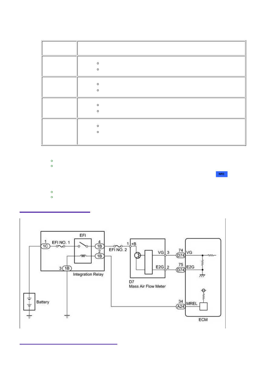
WIRING DIAGRAM
INSPECTION PROCEDURE
NOTICE:
Inspect the fuses for circuits related to this system before performing the following inspection
3UR-FE ENGINE CONTROL SYSTEM: SFI SYSTEM: P0102,P0103...