Content .. 1796 1797 1798 1799 ..
Toyota Tundra (2015 year). Manual - part 1798
11. INSTALL AIR TUBE SUB-ASSEMBLY
(a) Connect the 2 hoses.
(b) Install the air tube sub-assembly with the bolt.
Torque:
10 N·m {102 kgf·cm, 7ft·lbf}
12. INSTALL NO. 1 ENGINE COVER
13. INSTALL NO. 2 ENGINE COVER
14. INSTALL FRONT WATER BY-PASS JOINT
(a) Install 2 new gaskets and the front water by-pass joint with the 4 nuts to the cylinder head.
Torque:
21 N·m {214 kgf·cm, 15ft·lbf}
(b) Connect the No. 2 water by-pass hose to the front water by-pass joint, and slide the clamp to secure
the hose.
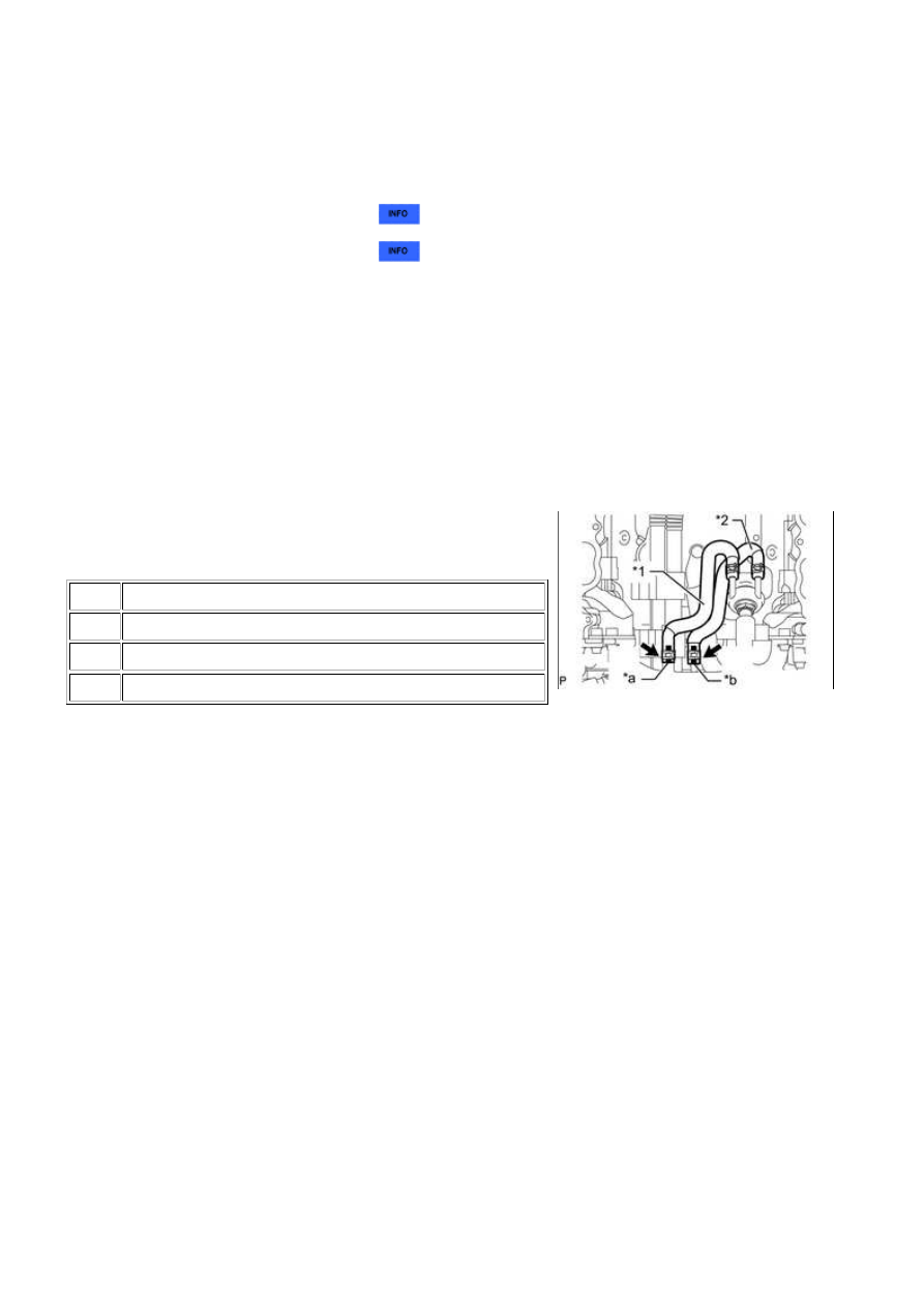
15. CONNECT NO. 10 WATER BY-PASS HOSE
(a) Connect the No. 10 water by-pass hose to the front water
by-pass joint, and slide the clamp to secure the hose.
Text in Illustration
*1
No. 9 Water By-pass Hose
*2
No. 10 Water By-pass Hose
*a
Paint Mark (Orange)
*b
Paint Mark (Yellow)
16. CONNECT NO. 9 WATER BY-PASS HOSE
(a) Connect the No. 9 water by-pass hose to the front water by-pass joint, and slide the clamp to secure
the hose.
17. INSTALL WATER BY-PASS PIPE SUB-ASSEMBLY
(a) Connect the No. 2 water by-pass hose and No. 3 water by-pass hose to the water by-pass pipe
sub-assembly, and slide the 2 clamps to secure the hoses.
(b) Install the water by-pass pipe sub-assembly with the 2 bolts.
Torque:
10 N·m {102 kgf·cm, 7ft·lbf}
(c) Connect the air tube sub-assembly with the bolt.
Torque:
10 N·m {102 kgf·cm, 7ft·lbf}
18. INSTALL NO. 1 WATER BY-PASS HOSE
(a) Connect the No. 1 water by-pass hose to the inlet water housing and front water by-pass joint, and
slide the 2 clamps to secure the hoses.
19. INSTALL GENERATOR ASSEMBLY
(a) Install the 2 stud bolts.
Torque:
3UR-FBE LUBRICATION: OIL PUMP: INSTALLATION; 2015 MY Tu...