Toyota Tundra (2015 year). Manual - part 1780


  Index      Toyota     Toyota Tundra (2015 year) - Service and Repair Manual


Search            copyright infringement  


Content   ..  1778  1779  1780  1781   ..


Toyota Tundra (2015 year). Manual - part 1780


Last Modified: 9-16-2014

6.6 A

Doc ID: RM0000031GO02MX

Model Year: 2015

Model: Tundra

Prod Date Range: [08/2014 -           ]

Title: 3UR-FBE INTAKE: INTAKE MANIFOLD: INSTALLATION; 2015 MY Tundra [08/2014 -        ]

INSTALLATION

1. INSTALL UNION TO CONNECTOR TUBE HOSE

(a) Install the 2 wire harness clamp brackets with the 2 bolts.

Torque:

8.0 N·m {82 kgf·cm, 71in·lbf}

(b) Install the union to connector tube hose to the intake manifold, and slide the clamp to secure the hose.

2. INSTALL PURGE VSV

(a) Connect the purge line hose to the intake manifold, and slide the clamp to secure the hose.

(b) Install the purge VSV with the bolt.

Torque:

21 N·m {214 kgf·cm, 15ft·lbf}

3. INSTALL VACUUM SWITCHING VALVE ASSEMBLY (for ACIS)

(a) Install the vacuum switching valve assembly with the bolt.

Torque:

9.0 N·m {92 kgf·cm, 80in·lbf}

(b) Connect the 2 vacuum hoses to the vacuum switching valve assembly.

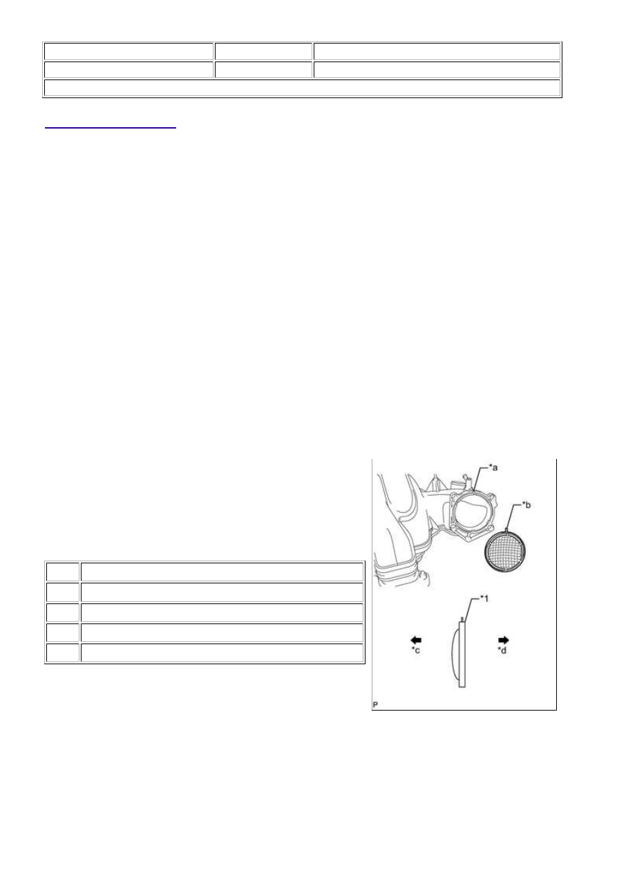
4. INSTALL THROTTLE BODY ASSEMBLY

Text in Illustration

*1

Gasket

*a

Groove

*b

Protrusion

*c

Intake Manifold Side

*d

Throttle Body Assembly Side

(b) Install the throttle body assembly with the 4 bolts.

Torque:

10 N·m {102 kgf·cm, 7ft·lbf}

5. INSTALL V-BANK COVER BOLT

(a) Install the 2 V-bank cover bolts to the intake manifold.

3UR-FBE INTAKE: INTAKE MANIFOLD: INSTALLATION; 2015 M...

Torque:

10 N·m {102 kgf·cm, 7ft·lbf}

6. INSTALL NO. 1 V-BANK COVER BRACKET

(a) Install the No. 1 V-bank cover bracket with the 2 bolts.

Torque:

10 N·m {102 kgf·cm, 7ft·lbf}

7. INSTALL VENTILATION HOSE ASSEMBLY

(a) Install the ventilation hose assembly to the intake manifold

with the 2 bolts.

Torque:

for bolt A -

21 N·m {214 kgf·cm, 15ft·lbf}

for bolt B -

10 N·m {102 kgf·cm, 7ft·lbf}

8. INSTALL INTAKE MANIFOLD

(a) Place 2 new gaskets on the intake manifold.

(b) Place the intake manifold on the cylinder head sub-assembly.

(c) Install and uniformly tighten the 8 bolts and 2 nuts in several steps.

Torque:

21 N·m {214 kgf·cm, 15ft·lbf}

(d) Install the wire harness clamp bracket to the intake manifold with the bolt.

Torque:

8.0 N·m {82 kgf·cm, 71in·lbf}

(e) Attach the 3 wire harness clamps to the 3 wire harness clamp brackets.

(f) Install the No. 1 tube with the 2 bolts.

Torque:

8.2 N·m {84 kgf·cm, 73in·lbf}

(g) Connect the union to connector tube hose to the No. 1 tube, and slide the clamp to secure the hose.

(h) Connect the purge line hose to the purge VSV, and slide the clamp to secure the hose.

(i) Connect the 2 vacuum switching valve connectors.

(j) Connect the ventilation hose to the intake manifold, and slide the clamp to secure the hose.

3UR-FBE INTAKE: INTAKE MANIFOLD: INSTALLATION; 2015 M...

(k) Connect the 2 water by-pass hoses to the inlet water housing and front water by-pass joint, and slide

the 2 clamps to secure the hose.

(l) Connect the throttle body connector to the throttle body assembly.

(m) Install the No. 3 engine cover.

(n) Install the No. 1 engine cover sub-assembly.

9. CONNECT VENTILATION HOSE ASSEMBLY

10. INSTALL AIR CLEANER HOSE ASSEMBLY

(a) Install the air cleaner hose assembly with the 2 hose clamps.

Torque:

4.0 N·m {41 kgf·cm, 35in·lbf}

(b) Connect the vacuum hose to the air cleaner hose assembly.

(c) Connect the ventilation hose to the air cleaner hose assembly, and slide the clamp to secure the hose.

11. INSTALL COWL TOP OUTER PANEL SUB-ASSEMBLY

(a) Install the cowl top outer panel sub-assembly with the 7 bolts.

Torque:

7.5 N·m {76 kgf·cm, 66in·lbf}

(b) Connect the washer hose and attach the 2 wire harness clamps.

12. INSTALL FRONT WIPER MOTOR AND LINK ASSEMBLY

13. ADD ENGINE COOLANT 

14. INSPECT FOR COOLANT LEAK 

15. INSTALL V-BANK COVER SUB-ASSEMBLY

(a) Attach the 2 V-bank cover hooks to the No. 1 V-bank cover

bracket. Then align the 2 V-bank cover grommets with the 2

pins, and press down on the V-bank cover sub-assembly to

attach the pins.

Text in Illustration

*1

V-bank Cover Grommet

*2

Pin

*3

No. 1 V-bank Cover Bracket

*4

V-bank Cover Hook

16. INSTALL NO. 1 ENGINE UNDER COVER 

3UR-FBE INTAKE: INTAKE MANIFOLD: INSTALLATION; 2015 M...

3UR-FBE INTAKE: INTAKE MANIFOLD: INSTALLATION; 2015 M...


Content   ..  1778  1779  1780  1781   ..