Toyota Tundra (2015 year). Manual - part 1736


  Index      Toyota     Toyota Tundra (2015 year) - Service and Repair Manual


Search            copyright infringement  


Content   ..  1734  1735  1736  1737   ..


Toyota Tundra (2015 year). Manual - part 1736


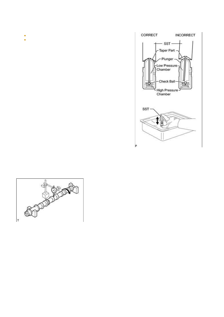
3. INSPECT VALVE LASH ADJUSTER ASSEMBLY

NOTICE:

Keep the adjuster free from dirt and foreign objects.
Use only clean engine oil.

tip to press down on the check ball inside the plunger.

SST: 09276-75010

(c) Squeeze SST and the lash adjuster together to move the

plunger up and down 5 to 6 times.

Plunger moves up and down.

NOTICE:

When bleeding high-pressure air from the compression

firmly press the plunger with your fingers.

OK:

Plunger can be pressed 3 times.

If the plunger can still be compressed after pressing it 3

times, replace the lash adjuster with a new one.

4. INSPECT CAMSHAFT SUB-ASSEMBLY

(a) Inspect the camshaft for runout.

(1) Place the camshaft on V-blocks.

(2) Using a dial indicator, measure the circle runout at the center journal.

Maximum circle runout:

0.04 mm (0.00157 in.)

If the circle runout is more than the maximum, replace the camshaft.

HINT:

Check the oil clearance after replacing the camshaft.

3UR-FBE ENGINE MECHANICAL: ENGINE UNIT: INSPECTION; ...

(b) Using a micrometer, measure the cam lobe height.

Standard cam lobe height:

ITEM

SPECIFIED CONDITION

Intake

44.291 to 44.441 mm (1.744 to 1.750 in.)

Exhaust

44.196 to 44.346 mm (1.740 to 1.746 in.)

Minimum cam lobe height:

ITEM

SPECIFIED CONDITION

Intake

44.241 mm (1.742 in.)

Exhaust

44.146 mm (1.738 in.)

If the cam lobe height is less than the minimum, replace the

camshaft.

(c) Using a micrometer, measure the journal diameter.

Standard journal diameter:

ITEM

SPECIFIED CONDITION

No. 1 journal

29.956 to 29.970 mm (1.1793 to 1.1799 in.)

Other journals

25.959 to 25.975 mm (1.0220 to 1.0226 in.)

If the journal diameter is not as specified, check the oil

clearance.

5. INSPECT CAMSHAFT TIMING GEAR

(a) Install the camshaft bearing cap 


.

HINT:

Only install the intake camshaft.

(b) Install the camshaft housing 


.

 Do not loosen or remove the 3 bolts shown in the illustration.

bolt.

Torque:

100 N·m {1020 kgf·cm, 74ft·lbf}

(g) Remove the camshaft bearing cap 


.

NOTICE:

Be careful not to damage the camshaft.

(i) Release the lock pin.

3UR-FBE ENGINE MECHANICAL: ENGINE UNIT: INSPECTION; ...

air pressure to the two broken paths.

NOTICE:

(4) Check that the camshaft timing gear revolves in the

advance direction when reducing the air pressure applied

to the retard side path.

HINT:

This operation releases the lock pin for the most retarded

position.

(5) When the camshaft timing gear reaches the most advanced position, release the air pressure from

the retard side path and advance side path, in that order.

NOTICE:

Do not release the air pressure from the advance side path first. The gear may abruptly shift in the

retard direction and break the lock pin.

(j) Check for smooth rotation.

(1) Turn the camshaft timing gear within its movable range (21°) 2 or 3 times, but do not turn it to the

most retarded position. Make sure that the gear turns smoothly.

NOTICE:

Do not use air pressure to perform the smooth rotation check.

(k) Check the lock in the most retarded position.

(1) Confirm that the camshaft timing gear is locked at the most retarded position.

(l) Install the camshaft bearing cap 


.

HINT:

Only install the intake camshaft.

(m) Install the camshaft housing 


.

(o) Remove the camshaft bearing cap 


.

3UR-FBE ENGINE MECHANICAL: ENGINE UNIT: INSPECTION; ...


Content   ..  1734  1735  1736  1737   ..