Content .. 1732 1733 1734 1735 ..
Toyota Tundra (2015 year). Manual - part 1734
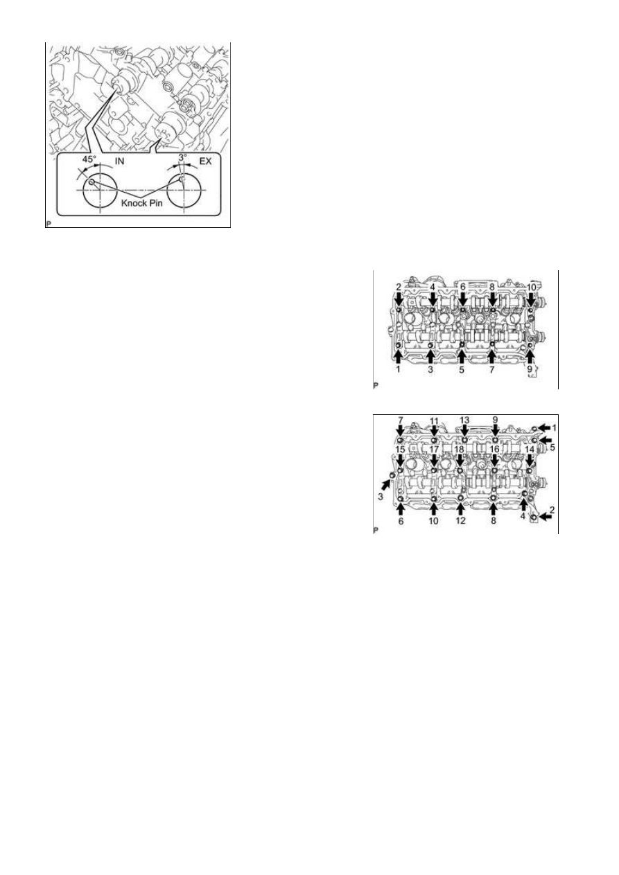
sequence shown in the illustration.
(c) Uniformly loosen and remove the 18 bearing cap bolts in the
sequence shown in the illustration.
NOTICE:
Uniformly loosen the bolts while keeping the camshaft level.
(d) Remove the 6 bearing caps.
HINT:
Arrange the removed parts in the correct order.
(e) Remove the No. 3 and No. 4 camshafts.
HINT:
Arrange the removed parts in the correct order.
35. REMOVE CAMSHAFT HOUSING SUB-ASSEMBLY LH
3UR-FBE ENGINE MECHANICAL: ENGINE UNIT: DISASSEMBLY;...