Content .. 1697 1698 1699 1700 ..
Toyota Tundra (2015 year). Manual - part 1699
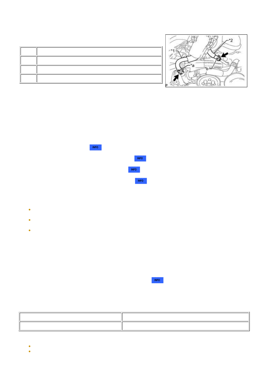
(g) Connect the No. 5 water by-pass hose to the water inlet
housing, and slide the clamp to secure the hose.
Text in Illustration
*1
No. 5 Water By-pass Hose
*2
No. 4 Water By-pass Hose
*a
Yellow Mark
*b
Pink Mark
HINT:
Make sure the hose color is shown in the illustration.
(h) Connect the No. 4 water by-pass hose to the No. 3 water by-pass pipe, and slide the clamp to secure
the hose.
HINT:
Make sure the hose color is shown in the illustration.
2. ADD ENGINE COOLANT
3. INSTALL AIR CLEANER HOSE ASSEMBLY
4. INSPECT FOR ENGINE COOLANT LEAK
5. INSTALL V-BANK COVER SUB-ASSEMBLY
6. PERFORM INITIALIZATION
NOTICE:
Be sure to perform this procedure after reassembling the throttle body assembly or removing and
reinstalling any throttle body component.
Perform the following procedure after replacing the ECM, throttle body assembly or any throttle body
components. The following procedure should also be performed if the throttle body is cleaned.
Be sure to perform this procedure after reconnecting the battery cable and replacing the ECM.
(a) Disconnect the EFI NO. 1 fuse and ETCS fuse at the same time. Wait at least 60 seconds and reconnect
the fuses.
(b) Turn the ignition switch to the ON position without operating the accelerator pedal.
NOTICE:
If the accelerator pedal is operated, perform the above steps again.
(c) Connect the Techstream to the DLC3 and clear the DTCs
.
(d) Start the engine and check that the MIL is not illuminated and that the idle speed is within the specified
range when the A/C is switched off after the engine is warmed up.
Standard:
CONDITION
ENGINE IDLE SPEED
A/C switched off
650 to 750 rpm
NOTICE:
Be sure to perform this step with all accessories off.
Make sure that the shift lever is in N or P.
(e) Enter the following menus: Powertrain / Engine and ETC / Data List / All Data / Throttle Sensor Position.
Sensor Output. Fully depress the accelerator pedal and check that the value is 60% or more.
3UR-FBE ENGINE CONTROL SYSTEM: THROTTLE BODY: INST...