Content .. 1686 1687 1688 1689 ..
Toyota Tundra (2015 year). Manual - part 1688
NEXT
13.
REPLACE FUEL PUMP ECU
(a) Replace the fuel pump ECU
.
14.
CONFIRM WHETHER MALFUNCTION HAS BEEN SUCCESSFULLY REPAIRED
(a) Check the fuel pump operation.
OK:
Malfunction has been repaired successfully.
NG
REPLACE ECM
OK
END
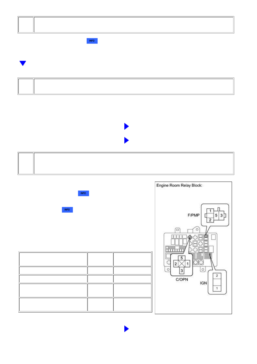
15.
CHECK HARNESS AND CONNECTOR (CIRCUIT OPENING RELAY - FUEL PUMP
RELAY AND IGN FUSE)
(a) Remove the circuit opening relay (C/OPN) from the
engine room relay block
.
(b) Remove the fuel pump relay (F/PMP) from the engine
room relay block
.
(c) Remove the IGN fuse from the engine room relay block.
(d) Measure the resistance according to the value(s) in the
table below.
Standard resistance:
TESTER CONNECTION
CONDITION
SPECIFIED
CONDITION
C/OPN relay (1) - IGN fuse (2)
Always
Below 1 Ω
C/OPN relay (3) - F/PMP relay (3)
Always
Below 1 Ω
C/OPN relay (1) or IGN fuse (2) -
Body ground
Always
10 kΩ or more
C/OPN relay (3) or F/PMP relay
(3) - Body ground
Always
10 kΩ or more
NG
REPAIR OR REPLACE HARNESS OR CONNECTOR
3UR-FBE ENGINE CONTROL SYSTEM: SFI SYSTEM: Fuel Pump C...