Content .. 1617 1618 1619 1620 ..
Toyota Tundra (2015 year). Manual - part 1619
A
RESULT
PROCEED
TO
Freeze frame data exists, but the starting difficulty cannot be reproduced and it is unknown what kind of
starting difficulty occurred
A
The problem symptoms can be reproduced, or the malfunction conditions are known
B
B
GO TO STEP 25
4.
CHECK FREEZE FRAME DATA
(a) Connect the Techstream to the DLC3.
(b) Turn the ignition switch to ON.
(c) Using the Techstream, confirm the vehicle conditions recorded in the freeze frame data which were
present when the DTC was stored
.
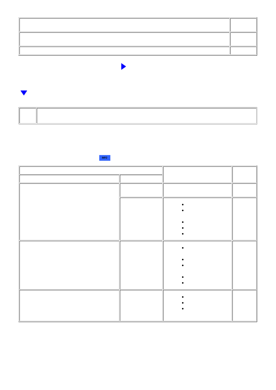
FREEZE FRAME DATA ITEM
SUSPECTED AREA
PROCEED
TO
ENGINE SPEED
BATTERY VOLTAGE
Minimum voltage is
less than 5 V
Battery fully depleted
A
Minimum voltage is
5 V or higher
Starter malfunction
Crankshaft position
sensor system
Excess engine friction
Immobiliser system
ECM
B
60 to 250 rpm (engine cranks but no initial
combustion)
-
Fuel pump control
system
Ignition system
Engine coolant
temperature sensor
Immobiliser system
Fuel injection system
C
250 rpm or higher (combustion occurs but initial
combustion and starter turnoff occur late)
-
Engine assembly
Fuel injection system
Fuel pump control
system
D
HINT:
When DTC P1604 is stored, either "Engine Start Hesitation"*1 or "Low Rev for Eng Start"*2 in the Freeze Frame
Data will be ON. If "Low Rev for Eng Start" is ON, proceed to E.
*2: This value turns ON when the engine stalls immediately after starting the engine. If "Low Rev for Eng Start" is
ON, as there is a possibility that the low engine speed or engine stall was caused by the user, confirm the following
3UR-FBE ENGINE CONTROL SYSTEM: SFI SYSTEM: P1604; Start...