Content .. 1601 1602 1603 1604 ..
Toyota Tundra (2015 year). Manual - part 1603
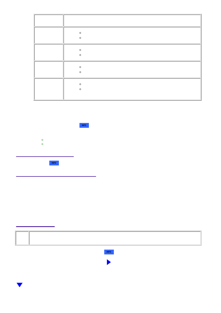
OK
TESTER
DISPLAY
DESCRIPTION
NORMAL
DTC judgment completed
System normal
ABNORMAL
DTC judgment completed
System abnormal
INCOMPLETE
DTC judgment not completed
Perform driving pattern after confirming DTC enabling conditions
N/A
Unable to perform DTC judgment
HINT:
If the judgment result shows ABNORMAL, the system has a malfunction.
If the test result is INCOMPLETE or N/A and no pending DTC is output, perform a universal trip and
check for permanent DTCs
.
HINT:
If a permanent DTC is output, the system is malfunctioning.
If no permanent DTC is output, the system is normal.
12.
WIRING DIAGRAM
Refer to DTC P0412
.
INSPECTION PROCEDURE
NOTICE:
Read freeze frame data using the Techstream. Freeze frame data records the engine condition when
malfunctions are detected. When troubleshooting, freeze frame data can help determine if the vehicle
was moving or stationary, if the engine was warmed up or not, if the air-fuel ratio was lean or rich, and
other data from the time the malfunction occurred.
PROCEDURE
1.
INSPECT AIR PUMP HEATER RELAY (AI HTR)
(a) Inspect the air pump heater relay (AI HTR)
.
NG
REPLACE AIR PUMP HEATER RELAY (AI HTR)
3UR-FBE ENGINE CONTROL SYSTEM: SFI SYSTEM: P144C,P144...