Toyota Tundra (2015 year). Manual - part 143
Last Modified: 9-16-2014
6.6 C
Doc ID: RM000004UD600XX
Model Year: 2015
Model: Tundra
Prod Date Range: [08/2014 - ]
Title: PARK ASSIST / MONITORING: BLIND SPOT MONITOR SYSTEM: C1AB5; Open in Outer Mirror
Indicator(Slave); 2015 MY Tundra [08/2014 - ]
DTC
C1AB5
Open in Outer Mirror Indicator(Slave)
DESCRIPTION
This DTC is stored when the blind spot monitor sensor LH detects an open in the blind spot monitor indicator LH.
DTC
CODE
DTC DETECTION CONDITION
TROUBLE AREA
C1AB5
With the blind spot monitor main switch assembly (warning canceling
switch assembly) on, the current flowing to the indicator is below a
specified value when indicator operation voltage is sent to the
indicator.
Harness or connector
Outer rear view
mirror sub-assembly
LH
Outer rear view
mirror assembly LH
Blind spot monitor
sensor LH
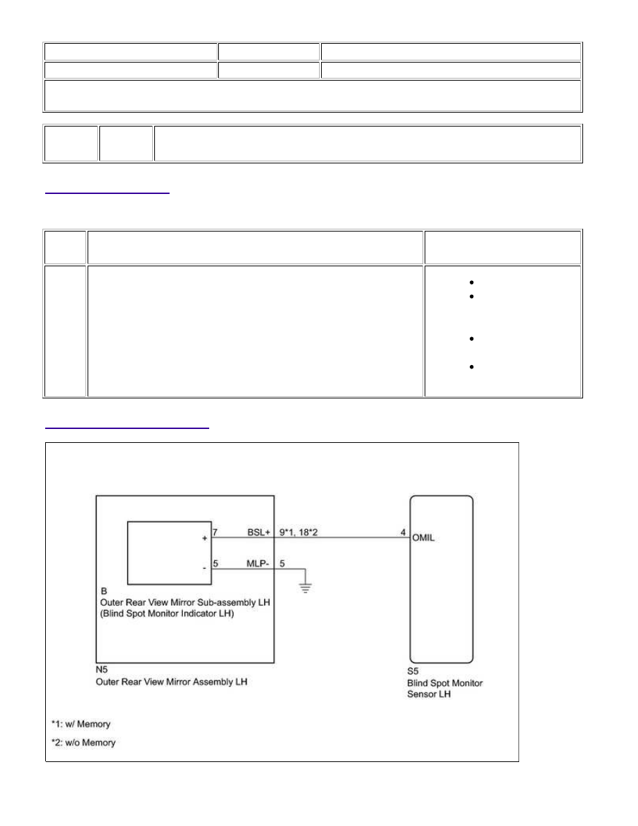
WIRING DIAGRAM
PARK ASSIST / MONITORING: BLIND SPOT MONITOR SYSTEM:...