Toyota Tundra (2015 year). Manual - part 130


  Index      Toyota     Toyota Tundra (2015 year) - Service and Repair Manual


Search            copyright infringement  


Content   ..  128  129  130  131   ..


Toyota Tundra (2015 year). Manual - part 130


Last Modified: 9-16-2014

6.6 D

Doc ID: RM000004RXS01PX

Model Year: 2015

Model: Tundra

Prod Date Range: [08/2014 -           ]

Title: PARK ASSIST / MONITORING: BLIND SPOT MONITOR SYSTEM: OPERATION CHECK; 2015 MY Tundra

[08/2014 -        ]

OPERATION CHECK

1. BLIND SPOT MONITOR BEAM AXIS INSPECTION

(a) Procedure to enter Test Mode

(1) Connect the Techstream to the DLC3.

(2) Turn the ignition switch to ON.

(3) Turn the blind spot monitor main switch assembly (warning canceling switch assembly) on.

(4) Turn the Techstream on.

(5) Switch the blind spot monitor sensor to Test Mode using the Techstream. Enter the following menus:

Body Electrical / Blind Spot Monitor Master or Blind Spot Monitor Slave / Utility / BSM Master beam axis

inspection or BSM Slave beam axis inspection.

(6) Finish Test Mode.

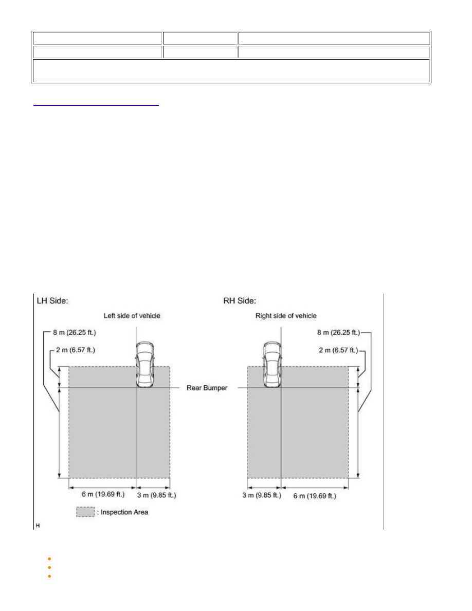
2. BLIND SPOT MONITOR BEAM AXIS CONFIRMATION

(a) When performing the blind spot monitor beam axis confirmation, move the vehicle to a place where the

space shown in the illustration can be secured.

NOTICE:

Perform this inspection on level ground.
Make sure that there are no metal objects around the vehicle or on the ground.
Unload the vehicle before beginning the inspection.

PARK ASSIST / MONITORING: BLIND SPOT MONITOR SYSTEM:...

Confirm that the tire pressure is correct before beginning the inspection.
Do not place an object other than the reflector (such as a large metallic object) in or allow people to enter
the inspection area (W 9 m (29.53 ft.) x L 10 m (32.81 ft.) x H 4 m (13.13 ft.)) shown in the illustration.
Check that DTC C1ABB and DTC C1ABC are not output.

(b) Place the reflector.

(2) Draw a vehicle center line so that it passes through mark (A)

and (B) (front and rear center points).

(3) Mark the position on the center line 684 to 704 mm (2.24 to

2.31 ft.) behind the rear bumper. (Mark (C))

from mark (C) as shown in the illustration.

PARK ASSIST / MONITORING: BLIND SPOT MONITOR SYSTEM:...

(6) Draw a line (P) so that it passes through mark (D) and (E)

and is perpendicular to the vehicle center line.

(7) Set the reflector at the position (Z) shown in the illustration below.

SST: 09870-60000

09870-60010

SST: 09870-60040

PARK ASSIST / MONITORING: BLIND SPOT MONITOR SYSTEM:...

NOTICE:

Set the reflector so that its center is 629 mm (2.06 ft.) above the ground.

(c) Perform the blind spot monitor beam axis display.

(1) Connect the Techstream to the DLC3.

(2) Turn the ignition switch to ON.

(3) Turn the blind spot monitor main switch assembly (warning canceling switch assembly) on.

(4) Turn the Techstream on.

(5) Enter the following menus: Body Electrical / Blind spot monitor Master or Blind spot monitor Slave /

Utility / BSM Master beam axis display or BSM Slave beam axis display.

PARK ASSIST / MONITORING: BLIND SPOT MONITOR SYSTEM:...


Content   ..  128  129  130  131   ..