Toyota Tundra (2015 year). Manual - part 1268


  Index      Toyota     Toyota Tundra (2015 year) - Service and Repair Manual


Search            copyright infringement  


Content   ..  1266  1267  1268  1269   ..


Toyota Tundra (2015 year). Manual - part 1268


A

OK

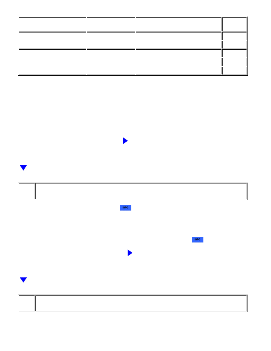
STATUS OF AFS VOLTAGE B1S1

OR AFS VOLTAGE B2S1

STATUS OF O2S B1S2

OR O2S B2S2

AIR FUEL RATIO CONDITION AND AIR

FUEL RATIO SENSOR CONDITION

PROCEED

TO

Lean

Lean

Actual air fuel ratio lean

A

Rich

Rich

Actual air fuel ratio rich

A

Lean

Lean/Rich

Air fuel ratio sensor malfunction

B

Rich

Lean/Rich

Air fuel ratio sensor malfunction

B

Lean/Rich

Lean/Rich

Normal

B

Lean: During the Control the injection Volume for A/F Sensor Active Test, the air fuel ratio sensor output voltage

(AFS Voltage) is consistently higher than 3.4 V, and the heated oxygen sensor output voltage (O2S) is

consistently below 0.4 V.

Rich: During the Control the injection Volume for A/F Sensor Active Test, the AFS Voltage is consistently below

3.1 V, and the O2S is consistently higher than 0.55 V.

B

GO TO STEP 16

6.

CHECK INTAKE SYSTEM

(a) Check the intake system for vacuum leaks 


.

OK:

No leaks in intake system.

HINT:

Perform "Inspection After Repair" after repairing or replacing the intake system 


.

NG

REPAIR OR REPLACE INTAKE SYSTEM

7.

CHECK FOR EXHAUST GAS LEAK

(a) Check for exhaust gas leak.

OK:

1UR-FE ENGINE CONTROL SYSTEM: SFI SYSTEM: P2195-P2198;...

OK

OK

OK

No gas leak

HINT:

Perform "Inspection After Repair" after repairing or replacing the exhaust system 


.

NG

REPAIR OR REPLACE EXHAUST SYSTEM

8.

CHECK FUEL PRESSURE

(a) Check the fuel pressure 


.

NG

GO TO STEP 18

9.

INSPECT FUEL INJECTOR ASSEMBLY

(a) Check the fuel injector (whether fuel volume is high or low, and whether injector pattern is poor)


.

HINT:

Perform "Inspection After Repair" after replacing the fuel injector assembly 


.

NG

REPLACE FUEL INJECTOR ASSEMBLY

10.

REPLACE AIR FUEL RATIO SENSOR

(a) Replace the air fuel ratio sensor 


.

HINT:

Perform "Inspection After Repair" after replacing the air fuel ratio sensor 


.

1UR-FE ENGINE CONTROL SYSTEM: SFI SYSTEM: P2195-P2198;...

NEXT

A

11.

PERFORM CONFIRMATION DRIVING PATTERN

(a) Connect the Techstream to the DLC3.

(b) Turn the ignition switch to ON.

(c) Turn the Techstream on.

(d) Clear the DTCs 


.

(e) Turn the ignition switch off and wait for at least 30 seconds.

(f) Turn the ignition switch to ON and turn the Techstream on.

(g) Start the engine and warm it up.

(h) Drive the vehicle in accordance with the driving pattern described in the Confirmation Driving

Pattern.

(i) Enter the following menus: Powertrain / Engine and ECT / Utility / All Readiness.

(j) Input the DTC: P2195, P2196, P2197 or P2198.

(k) Check the DTC judgment result.

Result

RESULT

PROCEED TO

ABNORMAL

(DTC P2195, P2196, P2197 or P2198 is output)

A

NORMAL

(DTC is not output)

B

B

END

12.

PERFORM ACTIVE TEST USING TECHSTREAM (CONTROL THE EGR STEP POSITION)

(a) Connect the Techstream to the DLC3.

(b) Start the engine and warm it up until the engine coolant temperature reaches 75°C (167°F) or

higher.

1UR-FE ENGINE CONTROL SYSTEM: SFI SYSTEM: P2195-P2198;...

OK

HINT:

When performing the Active Test, make sure the shift lever is in P or N.
The A/C switch and all accessory switches should be off.

(c) Turn the Techstream on.

(d) Enter the following menus: Powertrain / Engine and ECT / Active Test / Control the EGR Step

Position.

(e) Confirm the Throttle Idle Position is ON and check the engine idling condition and MAP values in the

Data List while performing the Active Test.

HINT:

Do not leave the EGR valve open for 10 seconds or more during the Active Test.
Be sure to return the EGR valve to step 0 when the Active Test is completed.

OK:

MAP and idling condition change in response to EGR step position as follows.

Standard:

-

EGR STEP POSITION (ACTIVE TEST)

0 STEPS

0 TO 30 STEPS

Idling

condition

Steady idling

Idling changes from steady to rough idling or engine stall

MAP

(Data List)

20 to 40 kPa (150 to 300

mmHg)

MAP value is at least +10 kPa (75 mmHg) higher than when EGR

valve is fully closed

OK

GO TO STEP 14

NG

GO TO STEP 13

13.

INSPECT EGR VALVE ASSEMBLY

(a) Remove the EGR valve assembly 


.

(b) Check if the EGR valve is stuck open.

OK:

EGR valve is tightly closed.

HINT:

Perform "Inspection After Repair" after repairing or replacing the EGR valve assembly 


.

NG

REPLACE EGR VALVE ASSEMBLY

1UR-FE ENGINE CONTROL SYSTEM: SFI SYSTEM: P2195-P2198;...


Content   ..  1266  1267  1268  1269   ..