Toyota Tundra (2015 year). Manual - part 1184


  Index      Toyota     Toyota Tundra (2015 year) - Service and Repair Manual


Search            copyright infringement  


Content   ..  1182  1183  1184  1185   ..


Toyota Tundra (2015 year). Manual - part 1184


A

GO TO STEP 5

B

GO TO STEP 6

4.

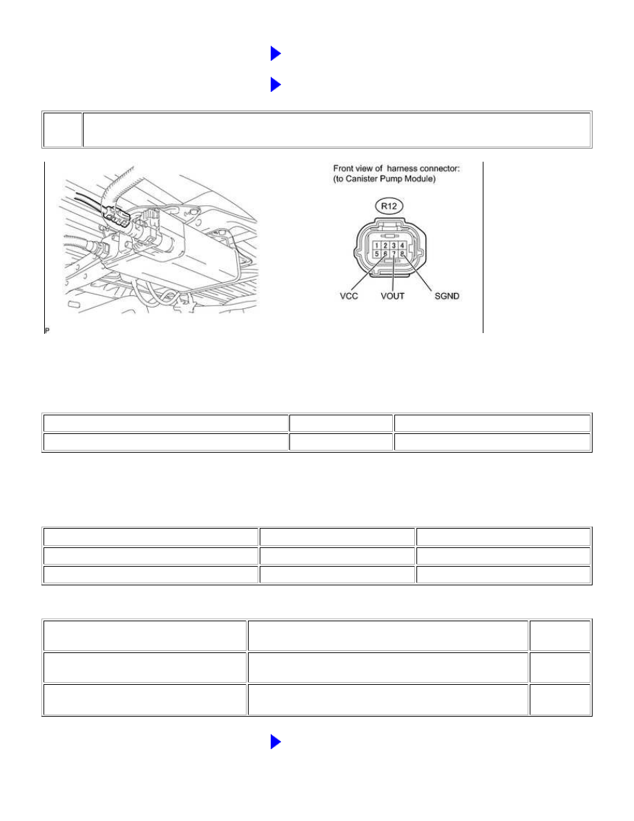
CHECK HARNESS AND CONNECTOR (CANISTER PUMP MODULE - ECM)

(a) Disconnect the canister pump module connector.

(b) Measure the resistance according to the value(s) in the table below.

Standard Resistance:

TESTER CONNECTION

CONDITION

SPECIFIED CONDITION

R12-8 (SGND) - Body ground

Always

100 Ω or less

(c) Turn the ignition switch to ON.

(d) Measure the voltage according to the value(s) in the table below.

Standard Voltage:

TESTER CONNECTION

SWITCH CONDITION

SPECIFIED CONDITION

R12-6 (VCC) - Body ground

Ignition switch ON

4.5 to 5.5 V

R12-7 (VOUT) - Body ground

Ignition switch ON

4.5 to 5.5 V

Result

RESULT

SUSPECTED TROUBLE AREA

PROCEED

TO

Voltage and resistance within standard

ranges

Open in canister pressure sensor circuit

A

Voltage and resistance outside standard

ranges

Open in wire harness/connector (ECM - Canister pressure

sensor)

B

B

GO TO STEP 6

1UR-FE ENGINE CONTROL SYSTEM: SFI SYSTEM: P0451-P0453;...

A

5.

REPLACE CANISTER PUMP MODULE

(a) Replace the canister pump module 


.

NOTICE:

When replacing the canister pump module, check the canister pump module interior, canister interior and related
pipes for water, fuel and other liquids. If liquids are present, check for disconnections and/or cracks in the following:
1) the pipe from the air inlet port to the canister pump module; 2) the canister filter; and 3) the fuel tank vent hose.
If liquids are present in the canister interior, replace the canister and canister pump module together.
Check for filter blockage in the canister. If the charcoal filter inside the canister is clogged, replace the canister and
canister pump module together.
Check for filter blockage in the canister filter. If the canister filter has blockages, replace the fuel tank inlet pipe
sub-assembly.

Text in Illustration

*1

Fuel Tank

*2

Fuel Tank Vent Hose

*3

Canister Assembly

*4

Canister Pump Module

- Canister Pressure Sensor

- Leak Detection Pump

- Vent Valve

*5

Fuel Tank Inlet Pipe Sub-assembly (Canister Filter)

*6

Canister Outlet Hose

*a

Inspection Area (check for disconnection and/or cracks)

-

-

NEXT

GO TO STEP 8

1UR-FE ENGINE CONTROL SYSTEM: SFI SYSTEM: P0451-P0453;...

NEXT

6.

REPAIR OR REPLACE HARNESS OR CONNECTOR (CANISTER PUMP MODULE - ECM)

HINT:

If the exhaust tailpipe has been removed, go to the next step before reinstalling it.

NEXT

GO TO STEP 8

7.

REPLACE ECM

(a) Replace the ECM 


.

8.

CHECK WHETHER DTC OUTPUT RECURS (AFTER REPAIR)

(a) Connect the Techstream to the DLC3.

(b) Turn the ignition switch to ON.

(c) Turn the Techstream on.

(d) Clear the DTCs 


.

(e) Turn the ignition switch off and wait for at least 30 seconds.

(f) Turn the ignition switch to ON and turn the Techstream on.

(g) Start the engine and warm it up.

(h) Drive the vehicle in accordance with the driving pattern described in the Confirmation Driving Pattern.

(i) Enter the following menus: Powertrain / Engine and ECT / Utility / All Readiness.

(j) Input the DTC: P0451, P0452 or P0453.

(k) Check the DTC judgment result.

TECHSTREAM DISPLAY

DESCRIPTION

NORMAL

DTC judgment completed

System normal

ABNORMAL

DTC judgment completed

System abnormal

INCOMPLETE

DTC judgment not completed

Perform driving pattern after confirming DTC enabling conditions

1UR-FE ENGINE CONTROL SYSTEM: SFI SYSTEM: P0451-P0453;...

TECHSTREAM DISPLAY

DESCRIPTION

N/A

Unable to perform DTC judgment

END

1UR-FE ENGINE CONTROL SYSTEM: SFI SYSTEM: P0451-P0453;...


Content   ..  1182  1183  1184  1185   ..