Content .. 1142 1143 1144 1145 ..
Toyota Tundra (2015 year). Manual - part 1144
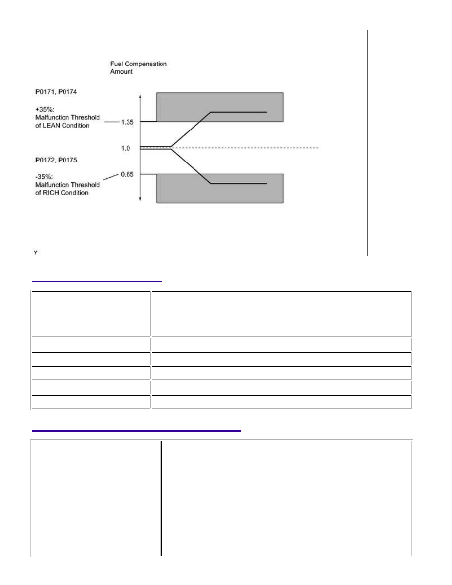
MONITOR STRATEGY
Related DTCs
P0171: Fuel trim lean (for Bank 1)
P0172: Fuel trim rich (for Bank 1)
P0174: Fuel trim lean (for Bank 2)
P0175: Fuel trim rich (for Bank 2)
Required Sensors/Components
Air fuel ratio sensor, Mass air flow meter, Crankshaft position sensor
Duration
Within 10 seconds
MIL Operation
2 driving cycles
TYPICAL ENABLING CONDITIONS
Monitor runs whenever following
DTCs not present
P0010, P0020 (VVT oil control valve)
P0011, P0021 (VVT system - Advance)
P0012, P0022 (VVT system - Retard)
P0013, P0023 (Exhaust VVT oil control valve)
P0014, P0024 (Exhaust VVT system - Advance)
P0015, P0025 (Exhaust VVT system - Retard)
P0016, P0018 (VVT system - Misalignment)
P0017, P0019 (Exhaust VVT system - Misalignment)
P0031, P0032, P0051, P0052, P101D, P103D (Air fuel ratio sensor
heater)
1UR-FE ENGINE CONTROL SYSTEM: SFI SYSTEM: P0171,P0172,...