Toyota Tundra (2015 year). Manual - part 5


  Index      Toyota     Toyota Tundra (2015 year) - Service and Repair Manual


Search            copyright infringement  


Content   ..  3  4  5  6   ..


Toyota Tundra (2015 year). Manual - part 5


Last Modified: 9-16-2014

6.6 F

Doc ID: RM000000UZ30F6X

Model Year: 2015

Model: Tundra

Prod Date Range: [08/2014 -           ]

ELECTRONIC CIRCUIT INSPECTION PROCEDURE

1. BASIC INSPECTION

(a) WHEN MEASURING RESISTANCE OF ELECTRONIC PARTS

(1) Unless otherwise stated, all resistance measurements should be made at an ambient temperature of

20°C (68°F). Resistance measurements may be inaccurate if measured at high temperatures, i.e.

immediately after the vehicle has been running. Measurements should be made after the engine has

cooled down.

(b) HANDLING CONNECTORS

(1) When disconnecting a connector, first squeeze the mating

halves tightly together to release the lock, and then press

the lock claw and separate the connector.

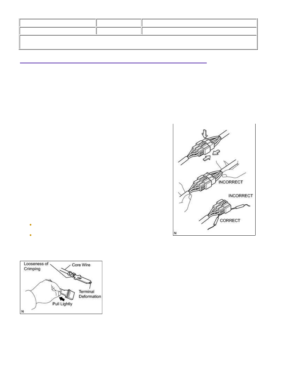
(2) When disconnecting a connector, do not pull on the

harnesses. Grasp the connector directly and separate it.

(3) Before connecting a connector, check that there are no

deformed, damaged, loose or missing terminals.

(4) When connecting a connector, press firmly until it locks with

a "click" sound.

(5) If checking a connector with a TOYOTA electrical tester,

check the connector from the backside (harness side) using a

mini test lead.

NOTICE:

(1) Checking when a connector is connected: Squeeze the connectors together to confirm that they are

fully connected and locked.

(2) Checking when a connector is disconnected: Check by pulling the wire harness lightly from the

conductor wires. Check visually for corrosion, metallic or foreign matter and water, and bent, rusted,

overheated, contaminated, or deformed terminals.

check for ample tension when inserting and after full

engagement.

NOTICE:

When testing a gold-plated female terminal, always use a

gold-plated male terminal.

(d) REPAIR METHOD OF CONNECTOR TERMINAL

(1) If there is any foreign matter on the terminal, clean the

contact point using an air gun or cloth. Never rub the contact

point using sandpaper as the plating may come off.

(2) If there is abnormal contact pressure, replace the female

terminal. If the male terminal is gold-plated (gold color), use

a gold-plated female terminal; if it is silver-plated (silver

color), use a silver-plated female terminal.

(3) Damaged, deformed, or corroded terminals should be

replaced. If the terminal does not lock into the housing, the

housing may have to be replaced.

(e) HANDLING OF WIRE HARNESS

(1) If removing a wire harness, check the wiring and clamping

before proceeding so that it can be restored in the same

way.

(2) Never twist, pull or slacken the wire harness more than

necessary.

(3) The wire harness should never come into contact with a high

temperature part, or rotating, moving, vibrating or

sharp-edged parts. Avoid contact with panel edges, screw

tips and other sharp items.

(4) When installing parts, never pinch the wire harness.

2. CHECK FOR OPEN CIRCUIT

(a) For an open circuit in the wire harness in Fig. 1, check the resistance or voltage, as described below.

(b) Check the resistance.

(1) Disconnect connectors A and C and measure the resistance between them.

Standard resistance (Fig. 2):

TESTER CONNECTION

SPECIFIED CONDITION

Connector A terminal 1 - Connector C terminal 1

10 kΩ or higher

Connector A terminal 2 - Connector C terminal 2

Below 1 Ω

HINT:

Measure the resistance while lightly shaking the wire harness vertically and horizontally.

(2) Disconnect connector B and measure the resistance between

the connectors.

Standard resistance (Fig. 3):

TESTER CONNECTION

SPECIFIED

CONDITION

Connector A terminal 1 - Connector B1

terminal 1

Below 1 Ω

Connector B2 terminal 1 - Connector C

terminal 1

10 kΩ or higher

If the results match the examples above, an open circuit

(c) Check the voltage.

(1) In a circuit in which voltage is applied to the ECU connector

terminal, an open circuit can be checked by conducting a

voltage check.

With each connector still connected, measure the voltage

between the body ground and these terminals (in this

Standard voltage (Fig. 4):

TESTER CONNECTION

SPECIFIED CONDITION

Connector A terminal 1 - Body ground

5 V

Connector B terminal 1 - Body ground

5 V

Connector C terminal 1 - Body ground

Below 1 V

If the results match the examples above, an open circuit

exists in the wire harness between terminal 1 of

(a) If the wire harness is ground shorted (Fig. 5), locate the section by conducting a resistance check with the

body ground (below).

(b) Check the resistance with the body ground.

(1) Disconnect connectors A and C and measure the resistance.

Standard resistance (Fig. 6):

TESTER CONNECTION

SPECIFIED CONDITION

Connector A terminal 1 - Body ground

Below 1 Ω


Content   ..  3  4  5  6   ..