Suzuki Grand Vitara JB627. Manual - part 379


  Index      Suzuki     Suzuki Grand Vitara JB627 - service repair manual


Search            


Content   ..  377  378  379  380   ..


Suzuki Grand Vitara JB627. Manual - part 379


9C-9 Instrumentation / Driver Info. / Horn: 

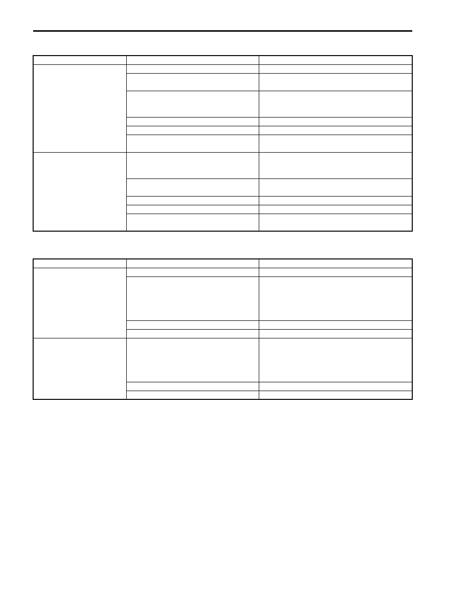
Illumination Indicator Symptom Diagnosis

S6JB0B9304009

Headlight Auto Leveling Indicator Symptom Diagnosis (If Equipped)

S6JB0B9304010

Condition

Possible cause

Correction / Reference Item

Illumination indicator 
does not light up

Circuit fuse blown

Replace fuse and check for short circuit.

Data (information) can not be received 
by CAN communication

Check BCM for DTC referring to “DTC Check 
in Section 10B”.

Lighting switch faulty

Check lighting switch referring to “Headlight 
Switch (in Lighting Switch) Inspection in 
Section 9B”
.

Wiring or ground faulty

Repair circuit.

Combination meter faulty

Replace combination meter.

BCM faulty

Replace after making sure that none of above 
parts is faulty.

Illumination indicator 
stays ON

Lighting switch faulty

Check lighting switch referring to “Headlight 
Switch (in Lighting Switch) Inspection in 
Section 9B”
.

Data (information) can not be received 
by CAN communication

Check BCM for DTC referring to “DTC Check 
in Section 10B”.

Wiring or ground faulty

Repair circuit.

Combination meter faulty

Replace combination meter.

BCM faulty

Replace after making sure that none of above 
parts is faulty.

Condition

Possible cause

Correction / Reference Item

Headlight auto leveling 
indicator does not light up

Circuit fuse blown

Replace fuse and check for short circuit.

Headlight auto leveling control module 
faulty

Check headlight auto leveling control module 
referring to “Inspection of Headlight Leveling 
Control Module and Its Circuit (Vehicle 
Equipped with Auto Leveling Headlight 
System) in Section 9B”.

Wiring or ground faulty

Repair circuit.

Combination meter faulty

Replace combination meter.

Headlight auto leveling 
indicator stays ON

Headlight auto leveling control module 
faulty

Check headlight auto leveling control module 
referring to “Inspection of Headlight Leveling 
Control Module and Its Circuit (Vehicle 
Equipped with Auto Leveling Headlight 
System) in Section 9B”.

Wiring or ground faulty

Repair circuit.

Combination meter faulty

Replace combination meter.

Instrumentation / Driver Info. / Horn:  9C-10

A/T Power Mode Indicator Symptom Diagnosis (A/T Model)

S6JB0B9304011

A/T Shift Position Indicator Symptom Diagnosis (A/T Model)

S6JB0B9304012

Charge Warning Light Symptom Diagnosis

S6JB0B9304013

Condition

Possible cause

Correction / Reference Item

A/T power mode indicator 
does not light up

Circuit fuse blown

Replace fuse and check for short circuit.

Data (information) can not be received 
by CAN communication

Check BCM for DTC referring to “DTC Check 
in Section 10B”.

A/T power mode switch faulty

Check mode select switch referring to “Mode 
Select Switch Inspection in Section 5A”.

Wiring or ground faulty

Repair circuit.

Combination meter faulty

Replace combination meter.

BCM faulty

Replace after making sure that none of above 
parts is faulty.

A/T power mode indicator 
stays ON

Data (information) can not be received 
by CAN communication

Check BCM for DTC referring to “DTC Check 
in Section 10B”.

A/T power mode switch faulty

Check mode select switch referring to “Mode 
Select Switch Inspection in Section 5A”.

Wiring or ground faulty

Repair circuit.

Combination meter faulty

Replace combination meter.

BCM faulty

Replace after making sure that none of above 
parts is faulty.

Condition

Possible cause

Correction / Reference Item

All A/T shift position 
indicator does not light up

Circuit fuse blown

Replace fuse and check for short circuit.

Data (information) can not be received 
by CAN communication

Check TCM for DTC referring to “DTC Check 
in Section 5A”.

Transmission range sensor (shift switch) 
faulty

Check transmission range sensor referring to 
“Transmission Range Sensor Inspection and 
Adjustment in Section 5A”.

Wiring or ground faulty

Repair circuit.

Combination meter faulty

Replace combination meter.

TCM faulty

Replace after making sure that none of above 
parts is faulty.

Condition

Possible cause

Correction / Reference Item

Charge warning light 
does not come ON

Circuit fuse blown

Replace fuse and check for short circuit.

Data (information) can not be received 
by CAN communication

Check BCM for DTC referring to “DTC Check 
in Section 10B”.

Wiring or ground faulty

Repair circuit.

Combination meter faulty

Replace combination meter.

BCM faulty

Replace after making sure that none of above 
parts is faulty.

Charge warning light stay 
ON

Charging system faulty

Check charging system.

Data (information) can not be received 
by CAN communication

Check BCM for DTC referring to “DTC Check 
in Section 10B”.

Wiring or ground faulty

Repair circuit.

Combination meter faulty

Replace combination meter.

BCM faulty

Replace after making sure that none of above 
parts is faulty.

9C-11 Instrumentation / Driver Info. / Horn: 

Main Beam (High Beam) Indicator Symptom Diagnosis

S6JB0B9304014

Warning Buzzer Circuit Symptom Diagnosis

S6JB0B9304015

NOTE

• Use of SUZUKI scan tool makes it easy to check whether a faulty condition is on the input side or 

output side of BCM. For checking procedure, refer to “Diagnosis Using Output Test Function of 
SUZUKI Scan Tool” under “Scan Tool Data in Section 10B”.

• Check each part in the order from the top of the following list.


Condition

Possible cause

Correction / Reference Item

Main beam (high beam) 
indicator does not come 
ON

Circuit fuse blown

Replace fuse and check for short circuit.

Data (information) can not be received 
by CAN communication

Check BCM for DTC referring to “DTC Check 
in Section 10B”.

Relay faulty

Replace relay

Combination switch faulty

Check combination switch referring to 
“Headlight Switch (in Lighting Switch) 
Inspection in Section 9B”.

Wiring or ground faulty

Repair circuit.

Combination meter faulty

Replace combination meter.

BCM faulty

Replace after making sure that none of above 
parts is faulty.

Main beam (high beam) 
indicator stay ON

Data (information) can not be received 
by CAN communication

Check BCM for DTC referring to “DTC Check 
in Section 10B”.

Combination switch faulty

Check combination switch referring to 
“Headlight Switch (in Lighting Switch) 
Inspection in Section 9B”.

Wiring or ground faulty

Repair circuit.

Combination meter faulty

Replace combination meter.

BCM faulty

Replace after making sure that none of above 
parts is faulty.

Condition

Possible cause

Correction / Reference Item

Warning buzzer shows no 
sounding

Circuit fuse blown

Replace fuse and check for short circuit.

Driver side door switch faulty

Check driver side door switch referring to 
“Door Switch (Front / Rear / Rear End Door) 
Inspection”.

Lighting switch faulty

Check lighting switch referring to “Headlight 
Switch (in Lighting Switch) Inspection in 
Section 9B”
.

Key remainder switch faulty

Check key remainder switch referring to 
“Ignition Switch Inspection”.

Wiring or ground faulty

Repair circuit.

BCM faulty

Replace after making sure that none of above 
parts is faulty.

Instrumentation / Driver Info. / Horn:  9C-12

Cigarette Lighter Symptom Diagnosis (If Equipped)

S6JB0B9304016

Horn Symptom Diagnosis

S6JB0B9304017

Information Display Symptom Diagnosis (If Equipped)

S6JB0B9304018

NOTE
This thermometer indicates the ambient temperature in back of front bumper. Under any one of the 
following listed conditions, however, even when the ambient temperature goes up, the thermometer 
display does not rise so as to correct the rise of the ambient temperature caused by the radiant heat of 
the engine. When the ambient temperature drops, the thermometer reading follows the change in the 
temperature.
Be sure to bear this in mind when diagnosing trouble.
• The vehicle speed is 30 km/h (18 mph) or lower.
• Vehicle speed signal is faulty.
• The ignition switch is turned on again within 2 hours.


Condition

Possible cause

Correction / Reference Item

Cigarette lighter shows 
no operation

Circuit fuse blown

Replace fuse and check for short circuit.

ACC relay faulty

Replace relay

Cigarette lighter faulty

Check cigarette lighter.

Ignition switch faulty

Check ignition switch referring to “Ignition 
Switch Inspection”.

Wiring or grounding faulty

Repair circuit.

Condition

Possible cause

Correction / Reference Item

Horn does not operate

Circuit fuse blown

Replace fuse and check for short circuit.

Horn switch faulty

Check horn switch.

Horn relay faulty

Check horn relay referring to “Horn Relay 
Inspection”.

Wiring or grounding faulty

Repair circuit.

Horn faulty

Check horn referring to “Horn Inspection”.

Condition

Possible cause

Correction / Reference Item

No displaying of 
information display

Circuit fuse Blown

Replace fuse and check for short circuit.

Wiring or grounding faulty

Repair as necessary.

Information display unit faulty

Replace unit.

Incorrect thermometer 
display

Outside air temperature sensor faulty

Check outside air temperature sensor referring 
to “Outside Air Temperature Sensor Inspection 
(If Equipped)”.

Vehicle speed signal faulty

Check ECM for DTC referring to “DTC Check 
in Section 1A”.

Wiring or grounding faulty

Repair as necessary.

Information display unit faulty

Replace unit.

BCM faulty

Replace after making sure that none of above 
parts is faulty.

Display does not change 
at –30 

°

C

Outside air temperature is –30 

°C (–22 

°F) or less

Outside air temperature sensor faulty

Check outside air temperature sensor referring 
to “Outside Air Temperature Sensor Inspection 
(If Equipped)”.

Information display unit faulty

Replace unit.

BCM faulty

Replace after making sure that none of above 
parts is faulty.


Content   ..  377  378  379  380   ..