Suzuki Grand Vitara JB627. Manual - part 314
8B-82 Air Bag System:
DTC B1324 / B1328: Left / Right Side-Air Bag Initiator Circuit Short to Power Circuit
S6JB0B8204035
Wiring Diagram
Refer to “DTC B1321 / B1325: Left / Right Side-Air Bag Initiator Circuit Resistance High”.
CAUTION
!
Be sure to observe instructions under CAUTION in “Air Bag Diagnostic System Check Flow”.
DTC Will Set when
The voltage measured at side-air bag (left or right) initiator circuit is above a specified value for specified time.
Flow Test Description
Step 1: Check whether malfunction is in side-air bag (inflator) module.
Step 2: Check side-air bag initiator circuit in floor harness.
Step 3: Check side-air bag initiator circuit in seat harness.
DTC Troubleshooting
Step
Action
Yes
No
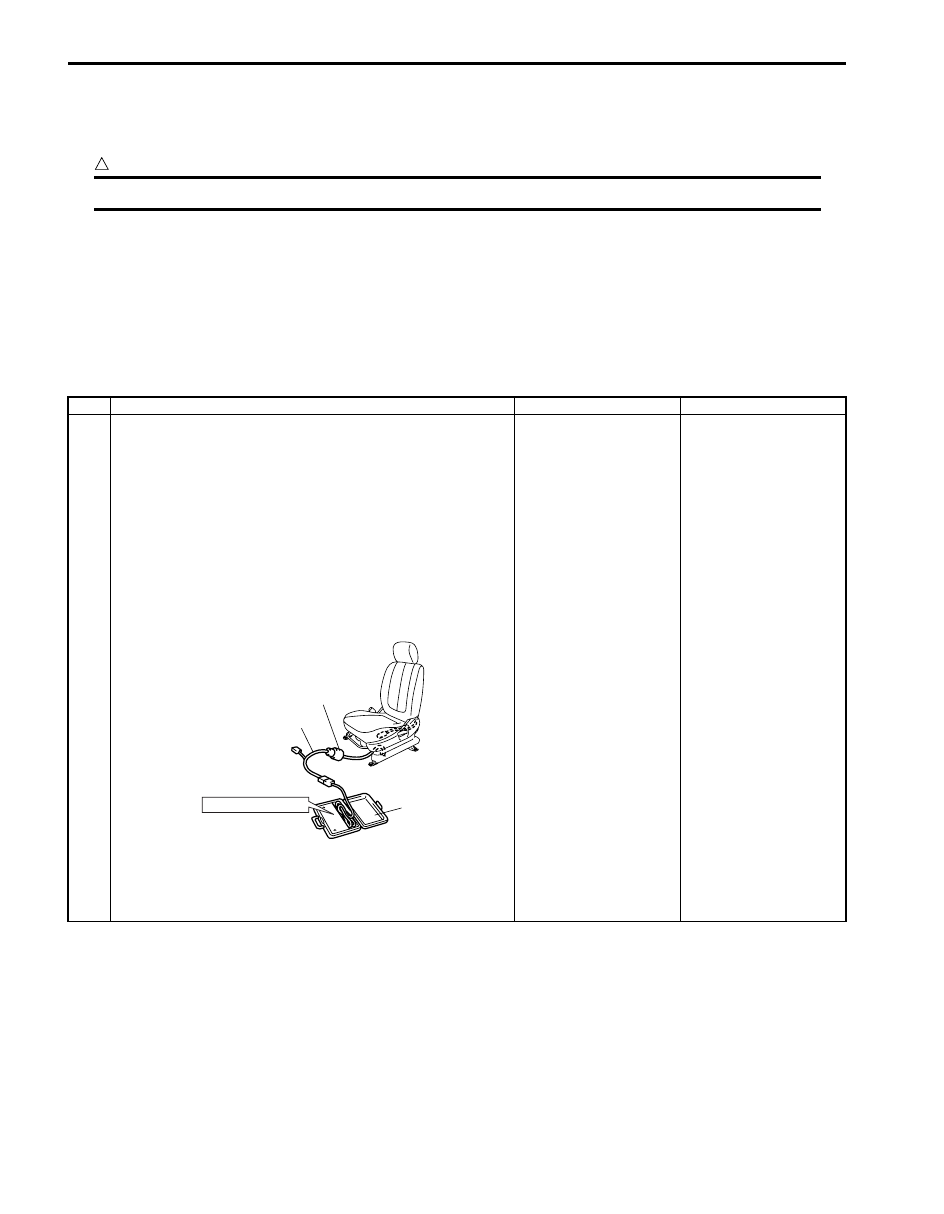
1
1) With ignition switch OFF, disconnect side-air bag
(inflator) module connector under front seat cushion.
2) Check proper connection to left or right side-air bag
(inflator) module at terminals in “L25” or “L30” connector.
3) If OK, then connect special tools (B) and (C) to side-air
bag (inflator) module connector disconnected at the Step
1.
Special tool
(B): 09932–75010
(C): 09932–78340
4) Check SDM DTC.
With ignition switch ON, is DTC B1324 or B1328 still
indicated?
Go to Step 2.
Go to Step 3.
“L25”, “L30”
(C)
(B)
STEERING WHEEL
I4RS0A820032-01