Suzuki Grand Vitara JB627. Manual - part 312
8B-74 Air Bag System:
2
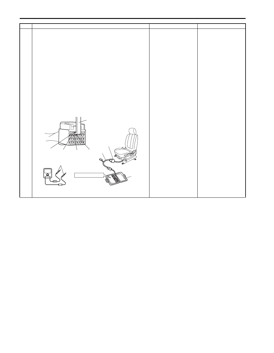
1) With ignition switch OFF, disconnect SDM connector
“L33”.
2) Check proper connection to SDM at terminals “L33-1”
and “L33-2” or “L33-3” and “L33-4”.
3) If OK, release shorting bar in SDM connector inserting
release tool (1) included in special tool (A).
4) Measure resistance between “L33-1” and “L33-2”
terminals (for DTC B1321) or “L33-3” and “L33-4”
terminals (for DTC B1325) with connected special tool
(B) and (C).
Special tool
(A): 09932–76010
(B): 09932–75010
(C): 09932–78340
Is resistance 5.5
Ω
or less?
Substitute a known-
good SDM and recheck.
DTC B1321: Repair
high resistance or open
in “GRY/RED” or “GRY”
wire circuit in floor
harness.
DTC B1325: Repair
high resistance or open
in “BRN/WHT” or “BRN”
wire circuit in floor
harness.
Step
Action
Yes
No
(A)
“L25”, “L30”
(C)
(B)
STEERING WHEEL
“L33-1”
“L33-2”
“L33-3 ”
“L33-4”
1, (A)
I5JB0A820045-01