Suzuki Grand Vitara JB627. Manual - part 252
5B-31 Manual Transmission/Transaxle:
NOTE
The specified tightening torque is also described in the following.
“Manual Transmission Assembly Components”
“Gear Shift Control Lever Rear Case Assembly Components”
“Gear Shift Lever Front Case Assembly Components”
“Gear Shift Shaft and Fork Components”
“Input Shaft Assembly, Output Shaft Assembly and Countershaft Assembly Components”
Reference:
For the tightening torque of fastener not specified in this section, refer to “Fastener Information in Section 0A”.
Special Tools and Equipment
Recommended Service Material
S6JB0B5208001
NOTE
Required service material is also described in the following.
“Manual Transmission Assembly Components”
“Gear Shift Control Lever Rear Case Assembly Components”
“Gear Shift Lever Front Case Assembly Components”
“Gear Shift Shaft and Fork Components”
“Input Shaft Assembly, Output Shaft Assembly and Countershaft Assembly Components”
Special Tool
S6JB0B5208002
Material
SUZUKI recommended product or Specification
Note
Grease
SUZUKI Super Grease A
P/No.: 99000–25010
Sealant
SUZUKI Bond No.1217G
P/No.: 99000–31260
Thread lock cement
Thread Lock Cement Super 1322
P/No.: 99000–32110
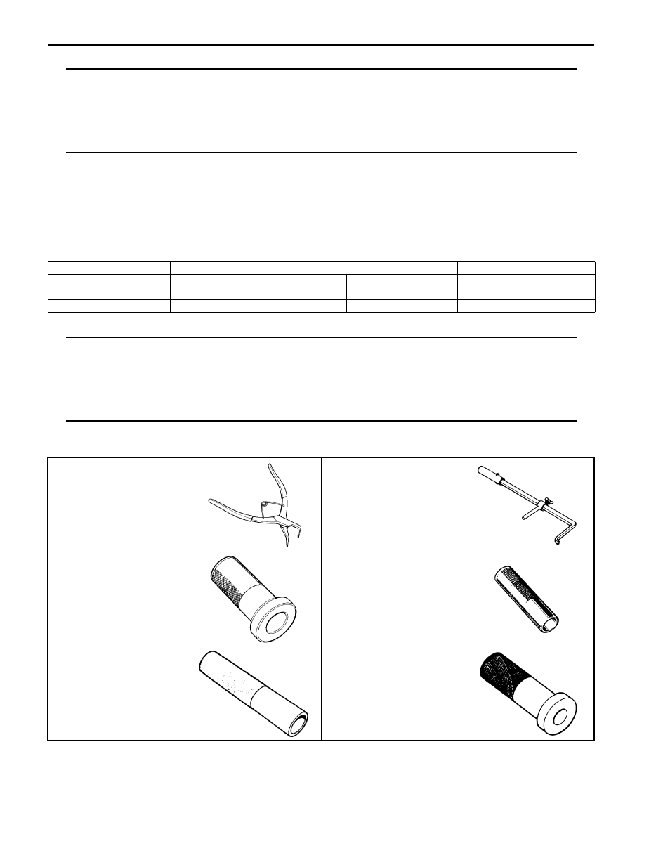
09900–06106
09913–50121
Snap ring pliers (closing
type)
Oil seal remover
09913–75810
09913–80113
Bearing installer
Bearing installer
09913–84510
09913–85210
Bearing installer
Bearing installer