Suzuki Grand Vitara JB627. Manual - part 250
5B-23 Manual Transmission/Transaxle:
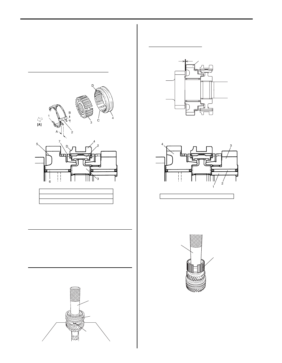
5) Assemble synchronizer sleeve (4) and hub (3) as
follows.
a) Fit high speed synchronizer sleeve to hub in
specified direction as shown in figure.
b) Insert 3 keys (2) to hub.
c) Set springs (1) at specified position as shown in
figure.
Synchronizer key installation position
: A = B
6) Drive in high speed synchronizer assembly (1) using
special tool and hammer.
NOTE
• While press-fitting sleeve & hub, make
sure that synchronizer ring key slots (2)
are aligned with keys in sleeve & hub
assembly.
• Check free rotation of 4th gear after press
fitting sleeve & hub assembly.
Special tool
(A): 09913–84510
7) Check 4th gear (1) thrust clearance by using
thickness gauge. If clearance is out of specification,
repress-fit or replace defective part.
4th gear thrust clearance
“a”: 0.10 – 0.25 mm (0.004 – 0.010 in.)
8) Apply oil to high speed gear needle bearing, and
then install 3rd gear bush (1), high speed gear
needle bearing (2) and 3rd gear (3).
9) Press-fit 5th speed synchronizer hub (1) using
special tool and hammer.
Special tool
(A): 09913–84510
[A]: 4th gear side
C: Key way
D: Projecting end
I5JB0A520060-01
(A)
1
2
I5JB0A520061-01
4. 4th gear
“a”
1
I5JB0A520062-01
I5JB0A520063-01
(A)
1
I5JB0A520064-01