Suzuki Grand Vitara JB627. Manual - part 221


  Index      Suzuki     Suzuki Grand Vitara JB627 - service repair manual


Search            


Content   ..  219  220  221  222   ..


Suzuki Grand Vitara JB627. Manual - part 221


5A-68 Automatic Transmission/Transaxle: 
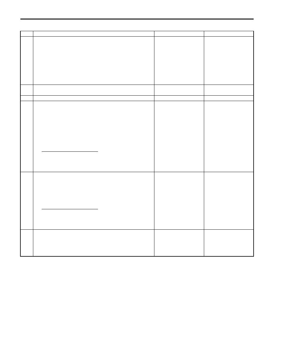
DTC Troubleshooting

Step

Action

Yes

No

1

Vehicle speed signal check
1) Check DTC in ECM and ABS control module referring to 

“DTC Check in Section 1A” and “DTC Check in Section 
4E”
.

Is there DTC P0500: Vehicle speed sensor (VSS) 
malfunction in ECM and/or DTC C1021, C1022, C1025, 
C1026, C1031, C1032, C1035 and/or C1036 in ABS control 
module?

Go to applicable DTC 
diag. flow.

Go to Step 2.

2

Was “A/T System Check” performed?

Go to Step 3.

Go to “A/T System 
Check”.

3

Do you have SUZUKI scan tool?

Go to Step 4.

Go to Step 5.

4

4L switch and its circuit check
1) Connect SUZUKI scan tool to DLC with ignition switch 

OFF.

2) Turn ignition switch ON.
3) Select “DATA LIST” mode on scan tool.
4) Check 4L/N switch signal (ON or OFF) on display when 

turning transfer position switch to each position.

4L/N switch specifications
“4H” position: OFF
“4L” position: ON

Is OFF / ON displayed as described above?

Intermittent trouble or 
faulty TCM. Check for 
intermittent trouble 
referring to “Intermittent 
and Poor Connection 
Inspection in Section 
00”. I
f OK, substitute a 
known-good TCM and 
recheck.

Go to Step 6.

5

4L/N switch and its circuit check
1) Turn ignition switch ON.
2) Check terminal voltage “E93-4” of TCM connector 

connected when turning transfer position switch to each 
position.

4L/N switch specifications
“4H” position: 10 – 14 V
“4L” position: 0 – 1 V

If voltage as specified?

Intermittent trouble or 
faulty TCM. Check for 
intermittent trouble 
referring to “Intermittent 
and Poor Connection 
Inspection in Section 
00”. I
f OK, substitute a 
known-good TCM and 
recheck.

Go to Step 6.

6

4L/N switch check
1) Check 4L/N switch for operation referring to “Transfer 

Assembly Inspection in Section 3C”.

Is check result satisfactory?

4L/N switch circuit open. 
If wire and connections 
are OK, substitute a 
known-good TCM and 
recheck.

Replace 4L/N switch.

Automatic Transmission/Transaxle:  5A-69

DTC P2742: Transmission Fluid Temperature Sensor “B” Circuit Low

S6JB0B5104042

Wiring Diagram

DTC Detecting Condition and Trouble Area

DTC Confirmation Procedure

1) Connect scan tool to DLC with ignition switch OFF.
2) Clear DTCs in TCM and ECM memories by using scan tool.
3) Start engine.
4) Keep engine running at idle speed for 1 minutes or more.
5) Check DTC, pending DTC and freeze-frame data.

DTC Troubleshooting

5V

E92-20

E92-10

GRY/BLU

GRY

2

1

3

6

5

16 15 14 13 12 11

4 3

24 23

21

22

10 9

8

7

2

1

19

20

18 17

E92

17 16

26 25

15 14

6

5

3

4

2

13 12

23 22

24

11 10 9

21 20 19

8 7

18

1

E93

I6JB01510015-01

1. Transmission fluid temperature sensor B

3. Terminal arrangement of TCM connector (viewed from harness side)

2. TCM

DTC Detecting Condition

Trouble Area

Transmission temperature sensor terminal voltage is less 
than 0.05 V for 6 minutes or more after ignition switch ON.
(1 driving cycle detection logic)

• Transmission fluid temperature sensor B or its circuit.
• TCM

Step

Action

Yes

No

1

Was “A/T System Check” performed?

Go to Step 2.

Go to “A/T System 
Check”
.

2

Check transmission fluid temperature sensor B circuit 
for ground short
1) Turn ignition switch OFF.
2) Disconnect TCM connectors from TCM.
3) Check for proper connection to transmission fluid 

temperature sensor B at terminal “E92-10” and “E92-20”.

4) If OK, check continuity between terminal “E92-20” of 

disconnected harness side TCM connector and ground.

Is continuity indicated?

Transmission fluid 
temperature sensor B 
signal circuit shorted to 
ground.

Go to Step 3.

3

Inspection transmission fluid temperature sensor B
1) Inspection transmission fluid temperature sensor B 

referring to “Transmission Fluid Temperature Sensor 
Inspection”.

Is check result satisfactory?

Intermittent trouble or 
faulty TCM. Check for 
intermittent trouble 
referring to “Intermittent 
and Poor Connection 
Inspection in Section 
00”. I
f OK, substitute a 
known-good TCM and 
recheck.

Replace valve body 
harness including 
transmission fluid 
temperature sensor B 
referring to 
“Transmission Fluid 
Temperature Sensor 
Removal and 
Installation”
.

5A-70 Automatic Transmission/Transaxle: 

DTC P2743: Transmission Fluid Temperature Sensor “B” Circuit High

S6JB0B5104043

Wiring Diagram
Refer to “DTC P2742: Transmission Fluid Temperature Sensor “B” Circuit Low”

DTC Detecting Condition and Trouble Area

DTC Confirmation Procedure

1) Connect scan tool to DLC with ignition switch OFF.
2) Clear DTCs in TCM and ECM memories by using scan tool.
3) Start engine and warm it up to normal operating temperature.
4) Start vehicle and increase vehicle speed to about 40 km/h (25 mile/h) in “D” range for 20 minutes or more.
5) Stop vehicle.
6) Check DTC, pending DTC and freeze-frame data.

DTC Troubleshooting

DTC Detecting Condition

Trouble Area

Transmission temperature sensor terminal voltage is less 
than 4.89 V under vehicle condition shown in the following.
• Ignition switch is turned on for 15 minutes or more
• Engine coolant temperature is more than 50 

°C (122 °F)

(1 driving cycle detection logic)

• Transmission fluid temperature sensor B or its 

circuit.

• TCM

Step

Action

Yes

No

1

Was “A/T System Check” performed?

Go to Step 2.

Go to“A/T System 
Check”.

2

Check transmission fluid temperature sensor B circuit 
for open
1) Turn ignition switch OFF.
2) Disconnect TCM connectors from TCM.
3) Check for proper connection to transmission fluid 

temperature sensor B at terminal “E92-10” and “E92-20”.

4) If OK, check continuity between terminal “E92-10” and 

“E92-20” of disconnected harness side TCM connector.

Is continuity indicated?

Go to Step 3.

Transmission fluid 
temperature sensor B 
signal or ground circuit 
is open circuit.

3

Check transmission fluid temperature sensor B circuit 
for IG short
1) Cool down A/T fluid temperature under ambient 

temperature.

2) Connect TCM connectors to TCM with ignition switch 

OFF.

3) Turn ignition switch ON.
4) Measure voltage between terminal “E92-20” of TCM 

connector and ground.

Is it 4.89 V or more?

Transmission fluid 
temperature sensor B 
signal circuit shorted to 
power supply circuit. If 
circuit is OK, go to Step 
4.

Intermittent trouble or 
faulty TCM. Check for 
intermittent trouble 
referring to “Intermittent 
and Poor Connection 
Inspection in Section 
00”.
 If OK, substitute a 
known-good TCM and 
recheck.

4

Inspection transmission fluid temperature sensor B
1) Inspection transmission fluid temperature sensor B 

referring to “Transmission Fluid Temperature Sensor 
Inspection”.

Is check result satisfactory?

Intermittent trouble or 
faulty TCM. Check for 
intermittent trouble 
referring to “Intermittent 
and Poor Connection 
Inspection in Section 
00”. I
f OK, substitute a 
known-good TCM and 
recheck.

Replace valve body 
harness including 
transmission fluid 
temperature sensor B 
referring to 
“Transmission Fluid 
Temperature Sensor 
Removal and 
Installation”.

Automatic Transmission/Transaxle:  5A-71

DTC P2763: Torque Converter Clutch (TCC) Circuit High

S6JB0B5104044

Wiring Diagram

DTC Detecting Condition and Trouble Area

DTC Confirmation Procedure

WARNING

!


• When performing a road test, select a place where there is no traffic or possibility of a traffic 

accident and be very careful during testing to avoid occurrence of an accident.

• Road test should be carried out with 2 persons, a driver and a tester, on a level road.


1) Connect scan tool to DLC with ignition switch OFF.
2) Clear DTCs in TCM and ECM memories by using scan tool.
3) Start engine.
4) Keep engine running at idle speed in “P” range for 10 seconds or more.
5) Check DTC, pending DTC and freeze-frame data.

1

2

12V

E92-3

E92-5

GRN/YEL

PPL/WHT

6

5

16 15 14 13 12 11

4 3

24 23

21

22

10 9

8

7

2

1

19

20

18 17

E92

17 16

26 25

15 14

6

5

3

4

2

13 12

23 22

24

11 10 9

21 20 19

8 7

18

1

E93

3

I5JB0A510027-01

1. TCC pressure control solenoid valve

3. Terminal arrangement of TCM connector (viewed from harness side)

2. TCM

DTC detecting condition

Trouble area

Voltage of TCC pressure control solenoid valve TCM terminal 
is high although TCM is commanding TCC pressure control 
solenoid to turn OFF.
(1 driving cycle detection logic)

• TCC pressure control solenoid valve circuit shorted 

to power circuit.

• Malfunction of TCC pressure control solenoid 

valve.

• TCM


Content   ..  219  220  221  222   ..