Suzuki Grand Vitara JB627. Manual - part 126


  Index      Suzuki     Suzuki Grand Vitara JB627 - service repair manual


Search            


Content   ..  124  125  126  127   ..


Suzuki Grand Vitara JB627. Manual - part 126


2B-18 Front Suspension: 

Installation

1) When installing stabilizer, loosely assemble all 

components while insuring that stabilizer is centered, 
side-to-side.

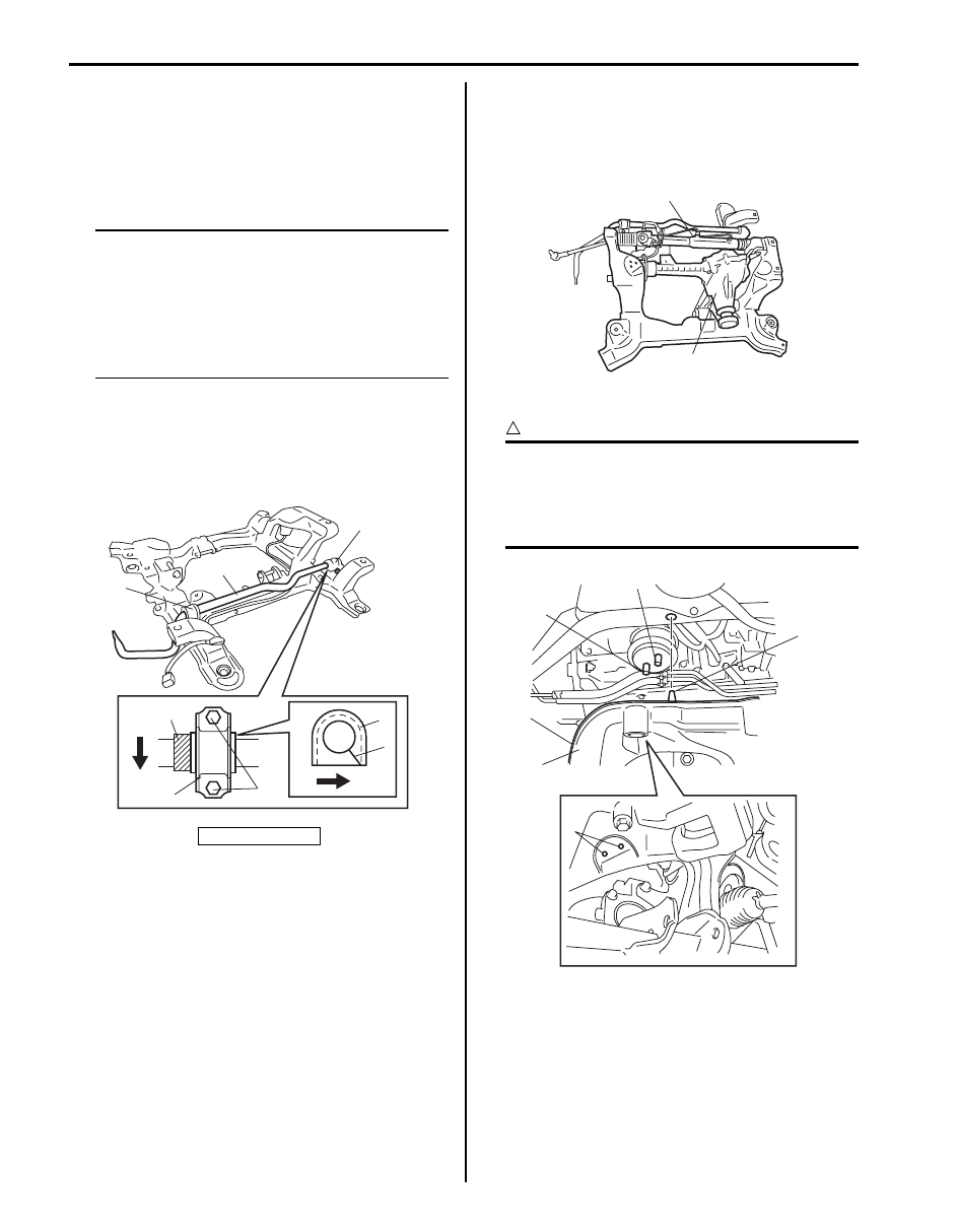
2) Install stabilizer bar (1), stabilizer bushing (2) and 

stabilizer mounting bracket (3) to suspension frame.

NOTE

• For correct installation of stabilizer bar, 

side-to-side, be sure that stopper ring (5) 
on stabilizer bar aligns with stabilizer 
bushing, both right and left, as shown in 
figure.

• Install stabilizer bushing so that a cut (6) 

becomes forward.


3) Tighten stabilizer bar mounting bracket bolts (4) to 

specified torque.

Tightening torque
Stabilizer bar mounting bracket bolt (a):  50 N·m (
5.0 kgf-m, 36.5 lb-ft)

4) Install P/S gear box assembly (1) and front 

differential assembly (2) referring to “P/S Gear Case 
Assembly Removal and Installation in Section 6C” 
and “Front Differential Dismounting and Remounting: 
Front in Section 3B”.

5) Install suspension frame.

CAUTION

!


Lug (2) in suspension frame (1) must be 
mated to the corresponding hole in body. 
And also engine front body side mounting 
bolts (3) must be mated to the corresponding 
holes (4) in suspension frame.


F: Forward

F

F

3

1

3

5

3

2

6

4, (a)

I5JB0D220003-02

1

2

I5JB0A220049-01

1

3

3

2

4

I6JB01220008-01

Front Suspension:  2B-19

6) Tighten suspension frame mounting bolts (1) and 

engine front body side mounting nuts (2) to specified 
torque.

CAUTION

!


If suspension frame mounting bolt is reused, 
apply engine oil to thread, bearing and trunk 
surface.


Tightening torque
Suspension frame mounting bolt (a):  135 N·m (
13.5 kgf-m, 98.0 lb-ft)
Engine front body side mounting nut (b):  55 N·m 
(5.5 kgf-m, 40.0 lb-ft)

7) Remove chain hoist from engine and the rope (1) 

from the radiator (2).

8) Install hood referring to “Hood Removal and 

Installation in Section 9J”.

9) Install front propeller shaft referring to “Propeller 

Shaft Removal and Installation in Section 3D”.

10) Install P/S oil line referring to the figure in “P/S Hose 

/ Pipe Components in Section 6C”.

11) Connect steering lower shaft from pinion shaft 

Steering referring to “Steering Lower Shaft Assembly 
Removal and Installation in Section 6B”.

12) Connect front height sensor connector (1) (if 

equipped with head light auto leveling system) and 
then detach clip (2).

13) Connect front fender lining clip (1) (if equipped with 

head light auto leveling system).

2,(b)

1,(a)

I6JB01220009-01

1

2

I5JB0A220046-01

1

2

I5JB0A220043-01

1

I5JB0A220042-01

2B-20 Front Suspension: 

14) Install stabilizer joints (1), and tighten nuts to 

specified torque. When tightening, hold stud with 
hexagon wrench.

Tightening torque
Stabilizer joint nut (a):  60 N·m (6.0 kgf-m, 43.5 
lb-ft)

15) Install right side and left side front drive shaft 

assembly referring to “Front Drive Shaft Assembly 
Removal and Installation: Front in Section 3A”
.

16) Install suspension control arm referring to 

“Suspension Control Arm Removal and Installation”.

17) Install engine under cover.
18) Install wheels (right & left) and lower hoist.
19) After installation, be sure to fill specified power 

steering fluid and bleed air referring to “P/S System 
Air Bleeding Procedure in Section 6C”.

20) Adjust auto leveling headlight system (if equipped), 

refer to “Initialization of Auto Leveling Headlight 
System in Section 9B”.

Front Suspension Frame Check

S6JB0B2206017

Inspect for cracks, deformation or damage.
If defective, replace.

Front Stabilizer Bar, Bushing and/or Joint 
Check

S6JB0B2206018

Stabilizer Bar
Inspect for damage or deformation.
If defective, replace.

Stabilizer Bushing
Inspect for damage, wear or deterioration.
If defective, replace.

Stabilizer Joint

1) Check for smooth rotation.
2) Check damages of ball stud.
3) Check damages of dust cover.

NOTE
Stabilizer joint (1) cannot be disassembled.


If there is any damage to either parts, stabilizer joint 
assembly must be replaced as a complete unit.

Front Suspension Fasteners Check

S6JB0B2206019

Check each bolt and nut fastening suspension parts for 
tightness. Tighten loose one, if any, to specified torque, 
referring to “Front Suspension Construction”.

(a)

1

1

(a)

I5JB0A220055-01

I5JB0A220056-01

I5JB0A220057-01

I5JB0D220002-01

1

I4RH01220007-01

Front Suspension:  2B-21

Specifications

Tightening Torque Specifications

S6JB0B2207001

NOTE
The specified tightening torque is also described in the following.
“Front Suspension Construction: ”
“Front Strut Assembly Components: ”
“Front Wheel Hub Assembly and Steering Knuckle Components: ”
“Front Suspension Frame, Stabilizer Bar and/or Bushings Components: ”


Reference:
For the tightening torque of fastener not specified in this section, refer to “Fastener Information in Section 0A”.

Fastening part

Tightening torque

Note

N

m

kgf-m

lb-ft

Tie-rod end lock nut

65

6.5 

47.0

)

Strut bracket nut

135

13.5 

98.0

)

 / )

Brake hose mounting bolt

25

2.5 

18.0

)

Stabilizer joint nut

60

6.0 

43.5

)

 / )

Wheel speed sensor harness clamp bolt

11

1.1 

8.0

)

Strut support nut

50

5.0 

36.5

)

Wheel nut

100

10.0 

72.5

)

 / ) / )

Strut nut

70

7.0 

51.0

)

Wheel hub housing bolt

50

5.0 

36.5

)

Caliper carrier bolt

85

8.5 

61.5

)

Drive shaft nut

220

22.0 

159.5

)

Suspension arm ball joint nut

55

5.5 

40.0

)

Wheel speed sensor bolt

11

1.1 

8.0

)

Tie-rod end nut

45

4.5 

32.5

)

Suspension control arm nut

135

13.5 

98.0

)

Stabilizer bar mounting bracket bolt

50

5.0 

36.5

)

Suspension frame mounting bolt

135

13.5 

98.0

)

Engine front body side mounting nut

55

5.5 

40.0

)


Content   ..  124  125  126  127   ..