Suzuki Grand Vitara JB627. Manual - part 118


  Index      Suzuki     Suzuki Grand Vitara JB627 - service repair manual


Search            


Content   ..  116  117  118  119   ..


Suzuki Grand Vitara JB627. Manual - part 118


1J-13 Charging System: 
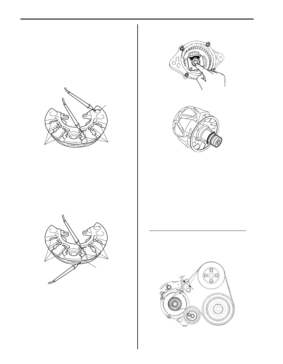
Rectifier
Positive rectifier

1) Using an ohmmeter, connect one tester probe to the 

“B” terminal (1) and the other to each rectifier 
terminal (2).

2) Reverse the polarity of the tester probes and repeat 

Step 1).

3) Check that one shows continuity and the other 

shows no continuity. If there is continuity, replace the 
rectifier.

Negative rectifier

1) Using an ohmmeter, connect one tester probe to 

negative terminal (1) and the other to each rectifier 
terminal (2).

2) Reverse the polarity of the tester probes and repeat 

Step 1).

3) Check that one shows continuity and the other 

shows no continuity. If there is continuity, replace the 
rectifier.

Bearing
• Check that drive and bearing is not rough or worn.

• Check that end housing bearing is not rough or worn.

Water Pump and Generator Drive Belt 
Inspection and Adjustment

S6JB0B1A06007

1) Disconnect negative cable at battery.
2) Inspect belt for cracks, cuts, deformation, wear and 

cleanliness. If it is necessary to replace belt, refer to 
“Water Pump and Generator Drive Belt Removal and 
Installation”.

3) Check belt for tension. Belt is in proper tension when 

it deflects the following specification under thumb 
pressure (about 10 kg or 22 lb.).

Water pump / generator drive belt tension “a”
Existing belt: 9.0 – 10.0 mm (0.35 – 0.39 in.) as 
deflection / 10 kg (22 lbs)
New belt: 7.5 – 8.5 mm (0.29 – 0.33 in.)as 
deflection / 10 kg (22 lbs)

1

2

2

I6JB011A0024-01

2

2

1

I6JB011A0025-01

IYSQ011A0050-01

I6JB011A0026-01

I6JB011A0027-01

Charging System:  1J-14

4) If belt is too tight or too loose, adjust it to proper 

tension as follows.
a) Loosen adjusting bolt (2) and remove tension 

pulley bolt (1). And then turn tension pulley (3) 
using hexagon wrench (4) as shown.

b) Adjust belt tension to specification, and then 

tighten adjusting bolt (2) and tension pulley bolt 
(1) to specified torque.

Tightening torque
Tension pulley bolt (a):  25 N·m (2.5 kgf-m, 
18.0 lb-ft)
Tension pulley adjusting bolt (b):  25 N·m (2.5 
kgf-m, 18.0 lb-ft)

Water Pump and Generator Drive Belt Removal 
and Installation

S6JB0B1A06008

Removal

1) Disconnect negative cable at battery.
2) Loosen tension pulley bolt (1) and tension pulley 

adjusting bolt (2).

3) Remove Water Pump and Generator Drive Belt (3).

Installation
Reverse removal procedure noting the following 
instruction.
• Adjust belt tension referring to “Water Pump and 

Generator Drive Belt Inspection and Adjustment”.

• Tighten all fasteners to specified torque.

Tightening torque
Tension pulley bolt (a):  25 N·m (2.5 kgf-m, 18.0 lb-ft)
Tension pulley adjusting bolt (b):  25 N·m (2.5 kgf-
m, 18.0 lb-ft)

1,(a)

2,(b)

4

3

I6JB0B1A0001-01

I6JB011A0028-01

I6JB011A0029-01

1J-15 Charging System: 

Specifications

Charging System Specifications

S6JB0B1A07001

Battery

Battery
: 55D23L(AH/5HR)12 V

Generator

Tightening Torque Specifications

S6JB0B1A07002

NOTE
The specified tightening torque is also described in the following.
“Generator Components”


Reference:
For the tightening torque of fastener not specified in this section, refer to “Fastener Information in Section 0A”.

Special Tools and Equipment

Special Tool

S6JB0B1A08001

Battery type

55D23L

Rated Capacity
AH/5HR, 12 Volts

48

Electrolyte
L (US/lmp. pt)

3.9

(8.24/6.86)

Electrolyte S. G.

1.28 when fully charged at 20 

°C (68 °F)

Type

115 A type

Rated voltage

12 V

Nominal output

115 A

Permissible max. speed

18000 r/min. (rpm)

No-load speed

1200 r/min. (rpm)

Setting voltage

14.2 – 14.8 V (at 20 

°C (68 °F))

Permissible ambient temperature

–30 – 90 

°C (–22 – 194 °F)

Polarity

Negative ground

Rotation

Clockwise viewed from pulley side

Fastening part

Tightening torque

Note

N

m

kgf-m

lb-ft

Generator bracket bolt

45

4.5 

32.5

)

Generator mounting upper bolt

25

2.5 

18.0

)

Generator mounting lower bolt

45

4.5 

32.5

)

“B” terminal outer nut

7

0.7 

5.0

)

“B” terminal nut 

9

0.9 

7.0

)

Pulley nut

118

11.8 

85.5

)

Frame bolt

4

0.4 

3.0

)

Tension pulley bolt

25

2.5 

18.0

)

 / )

Tension pulley adjusting bolt

25

2.5 

18.0

)

 / )

09913–76010

09943–88211

Bearing installer

Pinion bearing installer

)

)

Exhaust System:  1K-1

Engine

Exhaust System

Precautions

Exhaust System Caution

S6JB0B1B00001

NOTE
Be sure to use UNLEADED FUEL for the catalytic converter equipped vehicle. Use of LEADED FUEL 
will affect performance of the catalytic converter adversely to a great extent.


General Description

Exhaust System Description

S6JB0B1B01001

The exhaust system of the vehicle consists of the exhaust manifold (with Warm Up Three-Way Catalytic Convertor, 
WU-TWC), exhaust No.1 pipe, exhaust No.2 pipe (with Three-Way Catalytic Converter, TWC), muffler, seal, gasket, 
etc. The three way catalytic converter is an emission control device added to the exhaust system to lower the level of 
Hydrocarbon (HC), Carbon Monoxide (CO) and Oxides of Nitrogen (NOx) pollutants in the exhaust gas.

Diagnostic Information and Procedures

Exhaust System Check

S6JB0B1B04001

WARNING

!


To avoid the danger of being burned, do not touch the exhaust system when the system is hot. Any 
service on the exhaust system should be performed when the system is cool.


At every interval of periodic maintenance service, and when vehicle is raised for other service, check exhaust system 
as follows:
• Check rubber mountings for damage, deterioration, and out of position.

• Check exhaust system for leakage, loose connection, dent and damage.

If bolts or nuts are loosened, tighten them to specified torque. Refer to “Exhaust System Components”.

• Check under neath body for damaged, missing, mispositioned part, open seam, hole connection or any other defect 

which could permit exhaust fumes to seep into vehicle.

• Make sure that exhaust system components have enough clearance from underbody to avoid overheating and 

possible damage to passenger compartment carpet.

• Any defect should be fixed at once.

I6JB011B0001-01


Content   ..  116  117  118  119   ..