Suzuki Grand Vitara JB627. Manual - part 79


  Index      Suzuki     Suzuki Grand Vitara JB627 - service repair manual


Search            


Content   ..  77  78  79  80   ..


Suzuki Grand Vitara JB627. Manual - part 79


1C-14 Engine Electrical Devices: 

Knock Sensor Removal and Installation

S6JB0B1306020

Removal

1) Disconnect negative cable at battery.
2) Remove intake manifold from cylinder head referring 

to “Intake Collector and Intake Manifold Removal 
and Installation in Section 1D”.

3) Disconnect knock sensor connector (1).
4) Remove knock sensor (2) from cylinder block.

Installation
Reverse removal procedure for installation.

Tightening torque
Knock sensor (a):  22 N·m (2.2 kgf-m, 16.0 lb-ft)

Engine and Emission Control System Relay 
Inspection

S6JB0B1306021

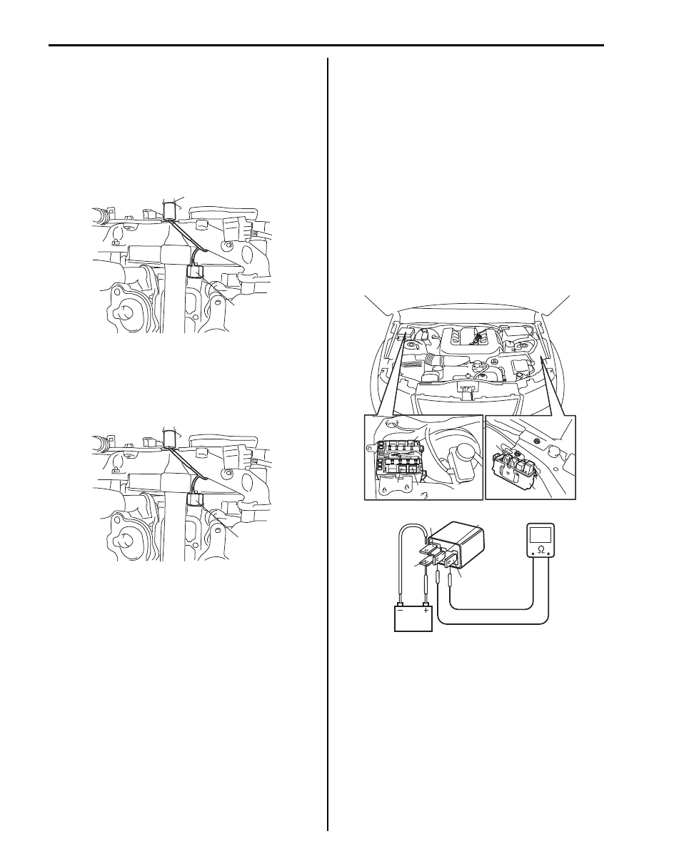
Main, Fuel Pump, Starting Motor Control and 
Throttle Actuator Control Relays (Single Type Relay)

1) Disconnect negative cable at battery.
2) Remove main relay (1), fuel pump relay (3), starting 

motor control relay (2), throttle actuator control relay 
(4) from fuse box No.2 (5) and/or relay box (6).

3) Check that there is no continuity between terminal 

“C” and “D”. If there is continuity, replace relay.

4) Connect battery positive (+) terminal to terminal “B” 

of relay. Connect battery negative (–) terminal to 
terminal “A” of relay. Check for continuity between 
terminal “C” and “D”. If there is no continuity when 
relay is connected to the battery, replace defective 
relay.

1

2

I6JB01130025-01

(a)

I6JB01130026-01

“D”

“B”

“A”

“C”

1

3

2

4

6

I5JB0C130001-01

Engine Electrical Devices:  1C-15

HO2S Heater Relay (Integration Type Relay)

1) Disconnect negative cable at battery.
2) Remove integration relay No.2 (1) from fuse box 

No.2 (2).

3) Check that there is no continuity between terminals 

“[A]-1” and “[B]-8” of relay.
If there is continuity, replace relay.

4) Connect battery positive (+) terminal to “[B]-7” 

terminal of relay. Connect battery negative (–) 
terminal to “[B]-6” terminal of relay. Check for 
continuity between terminal “[A]-1” and “[B]-8”. If 
there is no continuity when relay is connected to the 
battery, replace integration relay No.2.

IMT Vacuum Tank Assembly Inspection

S6JB0B1306022

CAUTION

!


Do not apply vacuum more than –86 kPa (– 
12.47 psi); otherwise IMT vacuum solenoid 
valve and vacuum tank could be damaged.


IMT vacuum solenoid valve

1) Disconnect negative cable at battery.
2) Remove vacuum tank assembly mounting bolts.
3) With ignition switch OFF, disconnect connector from 

IMT vacuum solenoid valve.

4) Check resistance of IMT vacuum solenoid valve.

If resistance is as specified, proceed to next 
operation check. If not, replace IMT vacuum 
solenoid valve.

Resistance of IMT vacuum solenoid valve
Between two terminals: 33 – 39 

 at 20 °C (68 °F)

5) Disconnect vacuum hoses (1 and 2) from IMT valve 

and vacuum tank.

6) With connector disconnected, apply vacuum (–53 

kPa (– 7.69 psi) to –67 kPa (–9.72 psi)) to hose (2).
Vacuum is maintained.

1. A/T relay
2. HO2S heater relay
3. Compressor relay

2

1

1

I5JB0C130002-01

1

1

2

3

4

5

6

7

8

1

2

3

4

5

6

7

8

“[B]-6”

[A]

[B]

“[A]-1”

“[B]-8”

“[B]-7”

[A]

[B]

1

2

3

I6JB01130038-01

I5JB0A130005-01

1

2

I5JB0A130006-01

1C-16 Engine Electrical Devices: 

7) With connector disconnected, apply vacuum to hose 

(1). Air goes into nozzle (2).

8) Connect 12 V-battery to IMT vacuum solenoid valve 

terminals. In this state, apply vacuum to hose (2). Air 
goes into hose (1).
If check result is not as described, replace IMT 
vacuum solenoid valve.

9) Connect vacuum hoses to IMT vacuum solenoid 

valve and IMT vacuum tank.

10) Connect IMT vacuum solenoid valve connector 

securely.

IMT Vacuum Tank

1) Check for outside of IMT vacuum tank visually.
2) Disconnect vacuum hoses from intake manifold and 

IMT vacuum solenoid valve.

3) Check for vacuum passage of IMT vacuum tank as 

follows by using vacuum pump.
a) When applying vacuum (– 53 kPa (– 7.69 psi) to 

– 67 kPa (–9.72 psi)) to hose (1), vacuum is 
maintained (there is no leakage): [A]

b) When applying vacuum to hose (2), vacuum is 

not maintained: [B]
If check result is not described, replace IMT 
vacuum tank assembly.

4) Connect vacuum hoses to intake manifold and IMT 

vacuum solenoid valve.

2

1

I5JB0A130007-01

2

1

I5JB0A130008-01

[B]

2

[A]

1

I5JB0A130009-01

Engine Electrical Devices:  1C-17

Specifications

Tightening Torque Specifications

S6JB0B1307001

Reference:
For the tightening torque of fastener not specified in this section, refer to “Fastener Information in Section 0A”.

Fastening part

Tightening torque

Note

N

m

kgf-m

lb-ft

MAF and IAT Sensor screw

1.5

0.15 

1.1

)

Accelerator pedal position (APP) sensor 
assembly nut

6.0

0.6 4.5

)

APP sensor assembly bracket nut

6.0

0.6 

4.3

)

ECT sensor

12

1.2 

8.5

)

MAP sensor bolt

5

0.5 

3.5

)

A/F sensor

45

4.5 

32.5

)

Heated oxygen sensor

45

4.5 

32.5

)

CMP sensor bolt

11

1.1 

8.0

)

CKP sensor bolt

11

1.1 

8.0

)

Knock sensor

22

2.2 

16.0

)


Content   ..  77  78  79  80   ..