Suzuki Grand Vitara JB627. Manual - part 78


  Index      Suzuki     Suzuki Grand Vitara JB627 - service repair manual


Search            


Content   ..  76  77  78  79   ..


Suzuki Grand Vitara JB627. Manual - part 78


1C-10 Engine Electrical Devices: 

• Between each terminal ((1), (2), (3) and (4)) of A/F 

sensor and A/F sensor body (5).

3) Connect A/F sensor connector securely.

Adjusting Resistor (If Equipped)

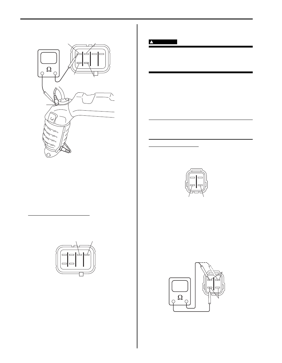
1) Disconnect A/F sensor connector.
2) Using ohmmeter, measure resistance of adjusting 

resistor between terminals “R+” and “R–” at A/F 
sensor connector.
If found faulty, replace A/F sensor.

Adjusting resistor resistance
100 – 58000 

 at 20 °C (68 °F)

Viewed from terminal side

3) Connect A/F sensor connector securely.

Heated Oxygen Sensor (HO2S-2) Heater On-
Vehicle Inspection (If Equipped)

S6JB0B1306014

WARNING

!


To avoid danger of being burned, do not 
touch exhaust system when system is hot. 
Sensor inspection should be performed 
when system is cool.


Heater

1) Disconnect sensor connector.
2) Using ohmmeter, measure resistance of sensor 

heater between terminals “V

B

” and “GND” at sensor 

connector.
If found faulty, replace oxygen sensor.

NOTE
Temperature of sensor affects resistance 
value largely. Make sure that sensor heater is 
at correct temperature.


HO2S heater resistance
5.0 – 6.4 

 at 20 °C (68 °F)

Viewed from terminal side

3) Connect sensor connector securely.

Circuit Insulation Check

1) Disconnect connector from HO2 sensor.
2) Using ohmmeter, check circuit insulation of HO2S 

sensor. If faulty is found, replace HO2S sensor.
• Between each heater terminal (1) and other than 

heater terminals (2).

Viewed from terminal side

1

2

3

4

5

I6JB01130035-01

“R+”

“R

I5JB0A130002-02

“GND”

“V

B

I5JB0A130024-03

1

2

I6JB01130036-01

Engine Electrical Devices:  1C-11

• Between each terminal ((1), (2), (3) and (4)) of 

HO2S sensor and HO2S sensor body (5).

3) Connect HO2S sensor connector securely.

Air Fuel Ratio (A/F) Sensor (Sensor-1) Removal 
and Installation

S6JB0B1306015

Removal

WARNING

!


To avoid danger of being burned, do not 
touch exhaust system when system is hot. A/
F sensor removal should be performed when 
system is cool.


1) Disconnect negative cable from battery.
2) Remove left or right bank of A/F sensor as follows:

• For left bank

a. Remove exhaust manifold cover from exhaust 

manifold.

b. Detach A/F sensor connector from bracket 

and then disconnect connector from A/F 
sensor. 

c. Remove A/F sensor from exhaust manifold.

• For right bank

a. Remove battery and battery tray from vehicle 

body.

b. Detach A/F sensor connector from bracket 

and then disconnect connector from A/F 
sensor.

c. Remove EGR pipe from exhaust manifold (if 

equipped).

d. Remove A/F sensor from exhaust manifold.

NOTE
Be careful not to expose it to excessive 
shock.


Example: Bank-2

Installation
Reverse removal procedure noting the followings.
• Tighten A/F sensor to specified torque.

Tightening torque
A/F sensor (a):  45 N·m (4.5 kgf-m, 32.5 lb-ft)

• Connect connector of A/F sensor and clamp wire 

harness securely.

• Install new gasket to EGR pipe (if equipped).
• After installing A/F sensor, start engine and check that 

no exhaust gas leakage exists.

1

2

3

4

5

I6JB01130037-02

1. Exhaust manifold cover
2. A/F sensor
3. EGR pipe (if equipped)
4. HO2S

1

3

2

4

I6JB01130017-03

(a)

I6JB01130030-01

1C-12 Engine Electrical Devices: 

Heated Oxygen Sensor (Sensor-2) Removal and 
Installation (If Equipped)

S6JB0B1306016

Removal

WARNING

!


To avoid danger of being burned, do not 
touch exhaust system when system is hot. 
Oxygen sensor removal should be performed 
when system is cool.


1) Disconnect negative cable from battery.
2) Detach oxygen sensor connector from bracket and 

then disconnect connector from oxygen sensor.

3) Remove oxygen sensor (1) from exhaust manifold 

(2).

NOTE
Be careful not to expose it to excessive 
shock.


Example: Bank-2

Installation
Reverse removal procedure noting the following.
• Tighten oxygen sensor to specified torque.

Tightening torque
Heated oxygen sensor (a):  45 N·m (4.5 kgf-m, 
32.5 lb-ft)

• Connect connector of oxygen sensor and clamp wire 

harness securely.

• After installing oxygen sensor, start engine and check 

that no exhaust gas leakage exists.

Camshaft Position (CMP) Sensor Removal and 
Installation

S6JB0B1306017

Removal

1) Disconnect negative cable at battery.
2) Disconnect connector from CMP sensor.
3) Remove CMP sensor (1) from timing chain cover.

Installation
Reverse removal procedure noting the following.
• Tighten CMP sensor bolt to specified torque.

Tightening torque
CMP sensor bolt (a):  11 N·m (1.1 kgf-m, 8.0 lb-ft)

• Connect CMP sensor connector securely.

3. A/F sensor

1

2

3

I6JB01130018-02

2. Coolant reservoir tank

(a)

I6JB01130031-02

1

2

I6JB01130019-01

(a)

I6JB01130020-01

Engine Electrical Devices:  1C-13

Crankshaft Position (CKP) Sensor Removal and 
Installation

S6JB0B1306018

Removal

1) Remove battery.
2) Disconnect connector from CKP sensor (1).
3) Remove CKP sensor from transmission case (2).

Installation
Reverse removal procedure noting the following.
• Tighten CKP sensor bolt to specified torque.

Tightening torque
CKP sensor bolt (a):  11 N·m (1.1 kgf-m, 8.0 lb-ft)

• Connect connector to CKP sensor securely.

Camshaft Position (CMP) Sensor and 
Crankshaft Position (CKP) Sensor Inspection

S6JB0B1306019

Visual check
• Check that O-ring is free from damage.
• Check that end face of sensor and signal rotor tooth 

are free from any metal particles and damage.

Performance check

1) Remove metal particles on end face of sensor, if any.
2) Arrange 12 V battery (1) and connect its positive 

terminal to “Vin” terminal (2) and negative terminal to 
“Ground” terminal (3) of sensor. Then using 
ohmmeter, measure resistance between “Vout” 
terminal (4) of sensor and negative terminal of 
battery by passing magnetic substance (iron) (5) 
while keeping approximately 1 mm (0.03 in.) gap 
with respect to end face of sensor.
If resistance does not vary as specified below, 
replace defective sensor.

CMP or CKP sensor resistance
Resistance varies from less than 220 

 (ON) to 

infinity (OFF) or from infinity (OFF) to less than 
220 

 (ON)

1

2

I6JB01130021-01

(a)

I6JB01130022-01

I6JB01130023-01

I6JB01130024-01


Content   ..  76  77  78  79   ..